
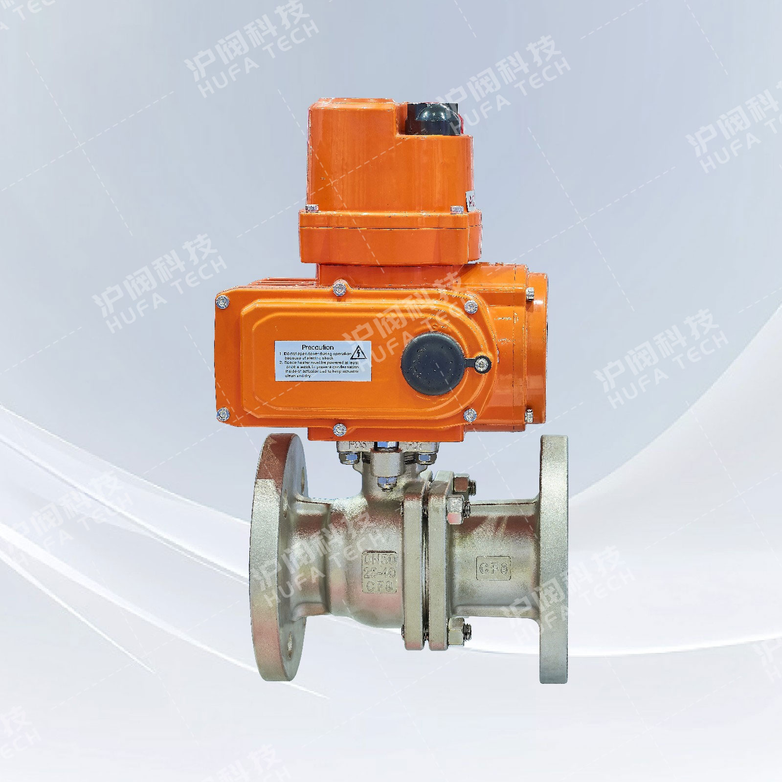
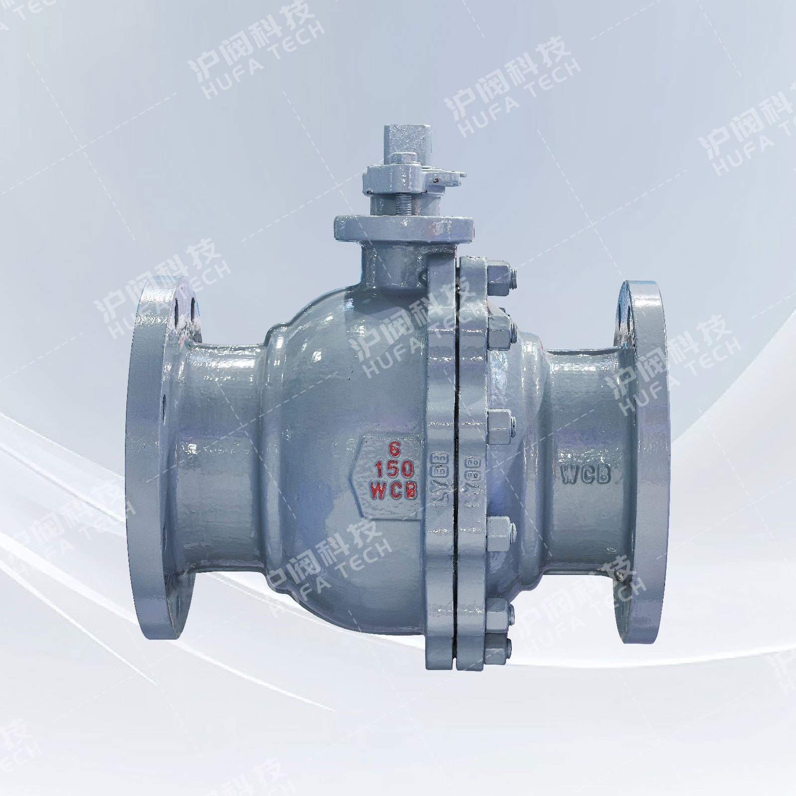
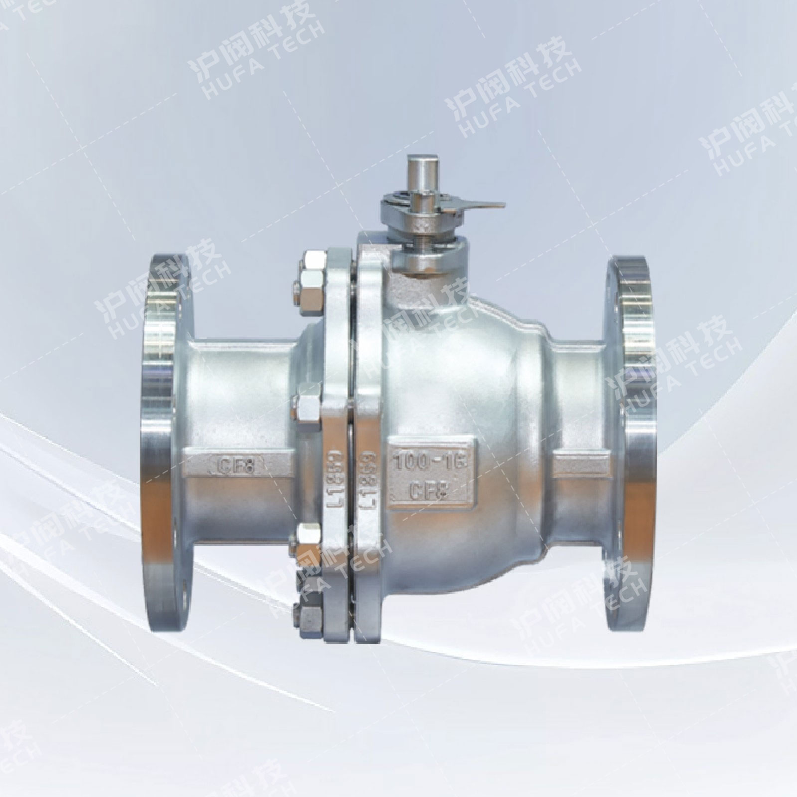
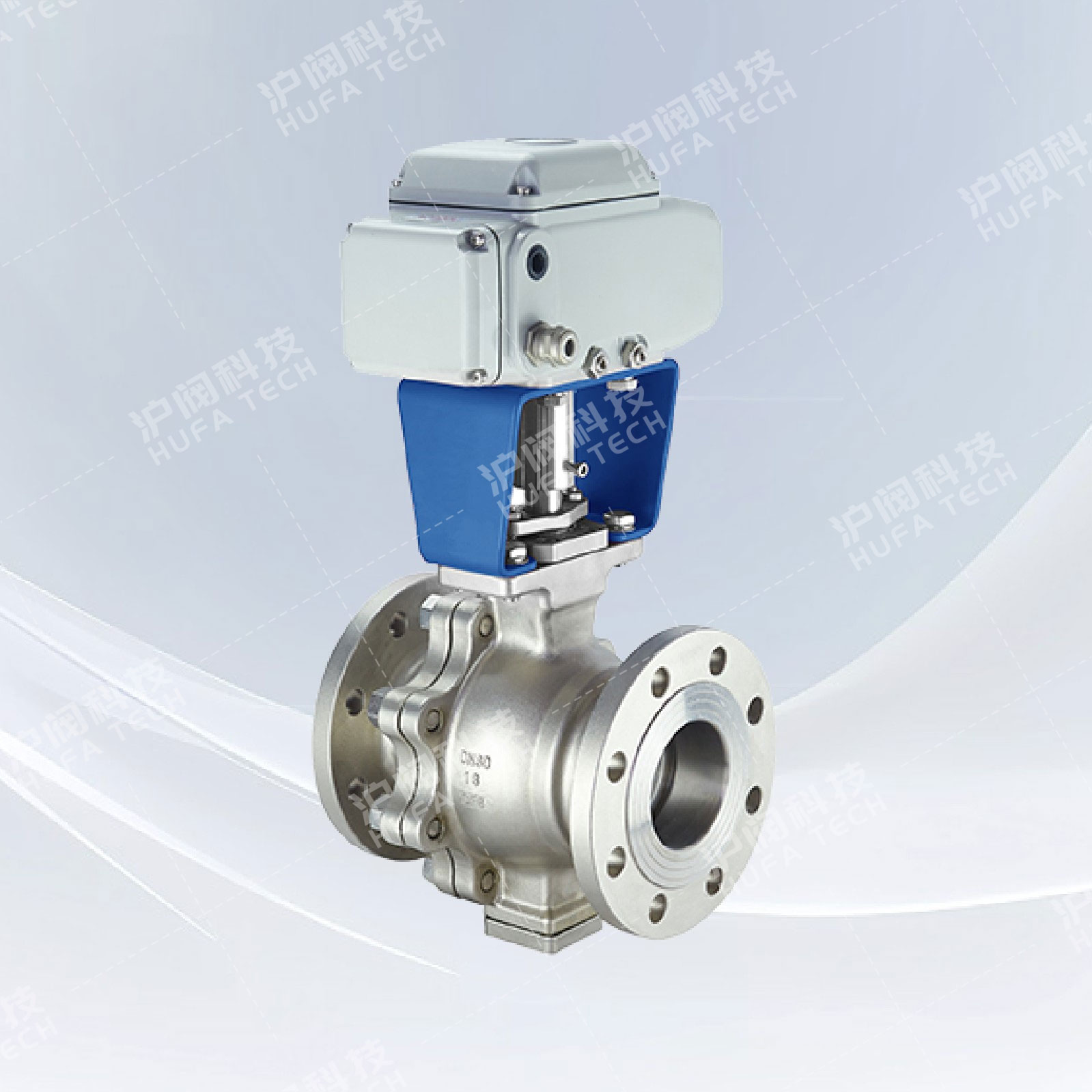
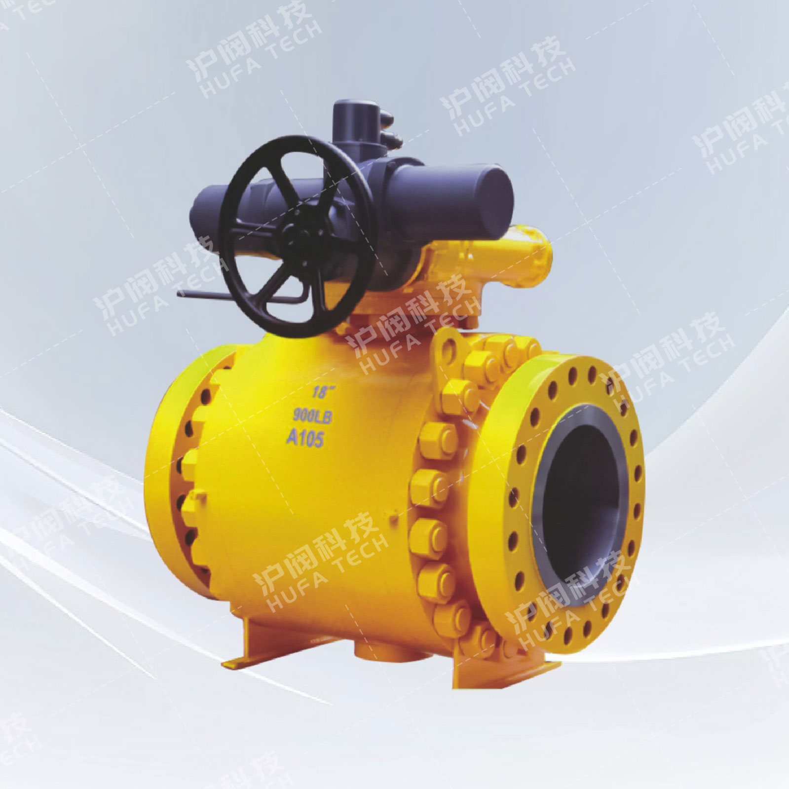
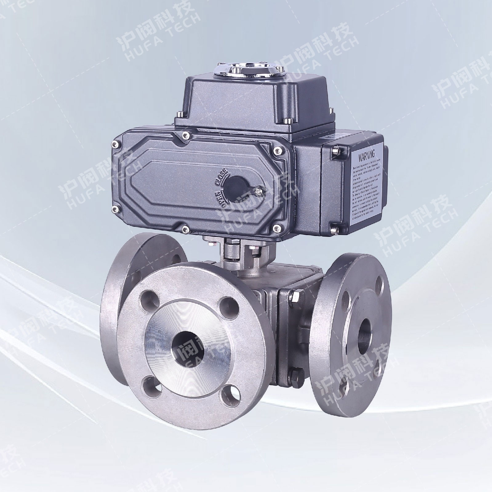
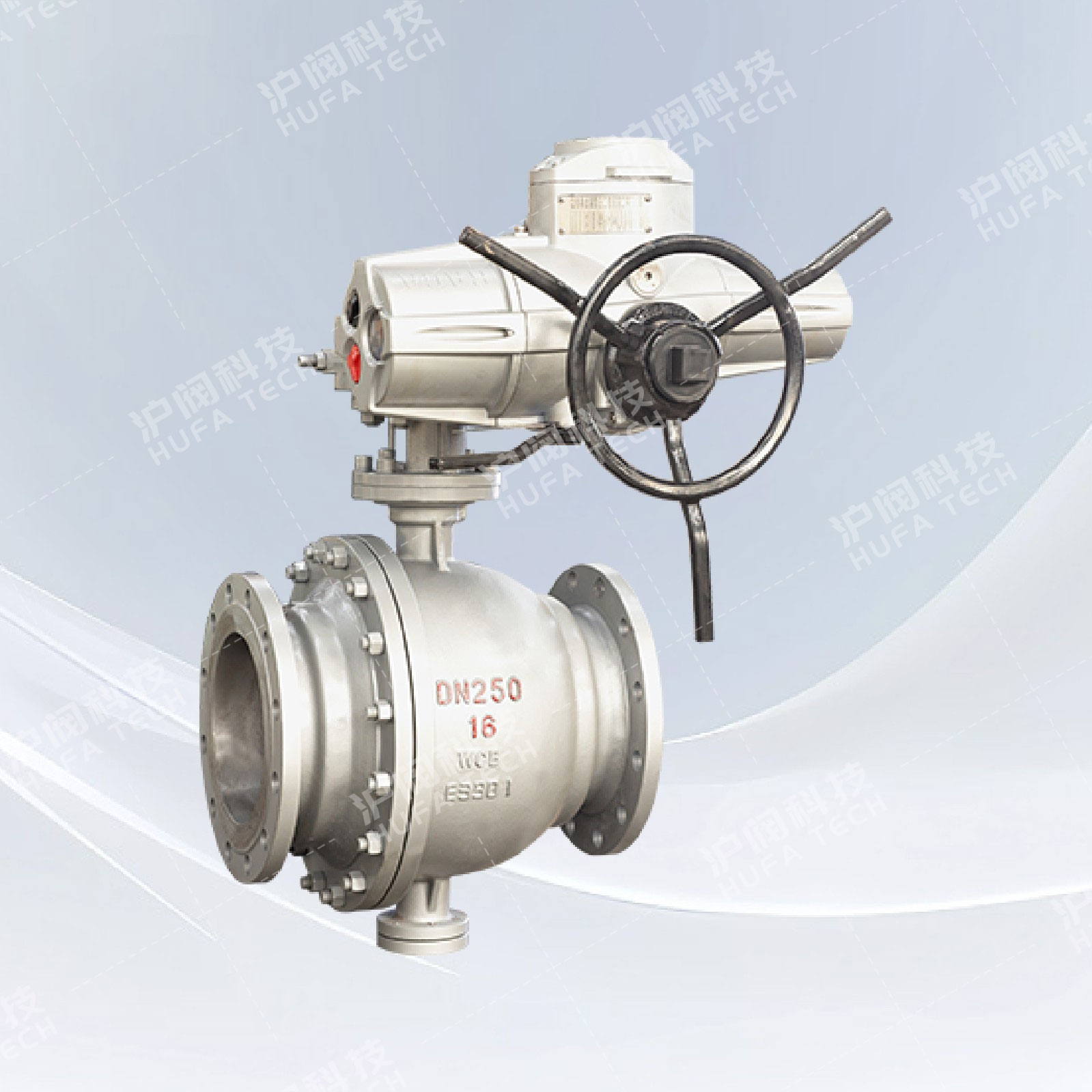
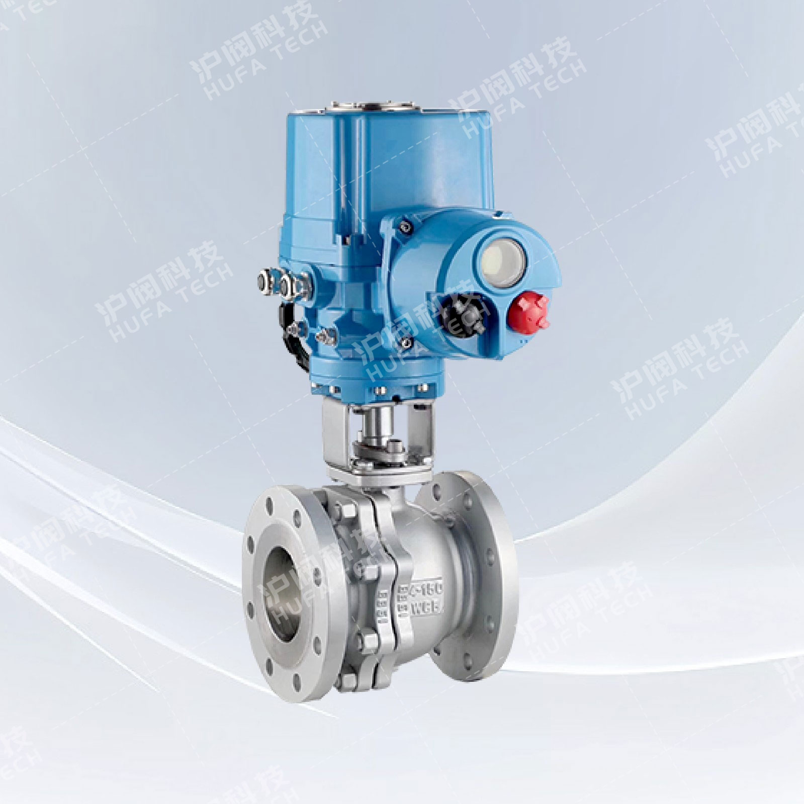
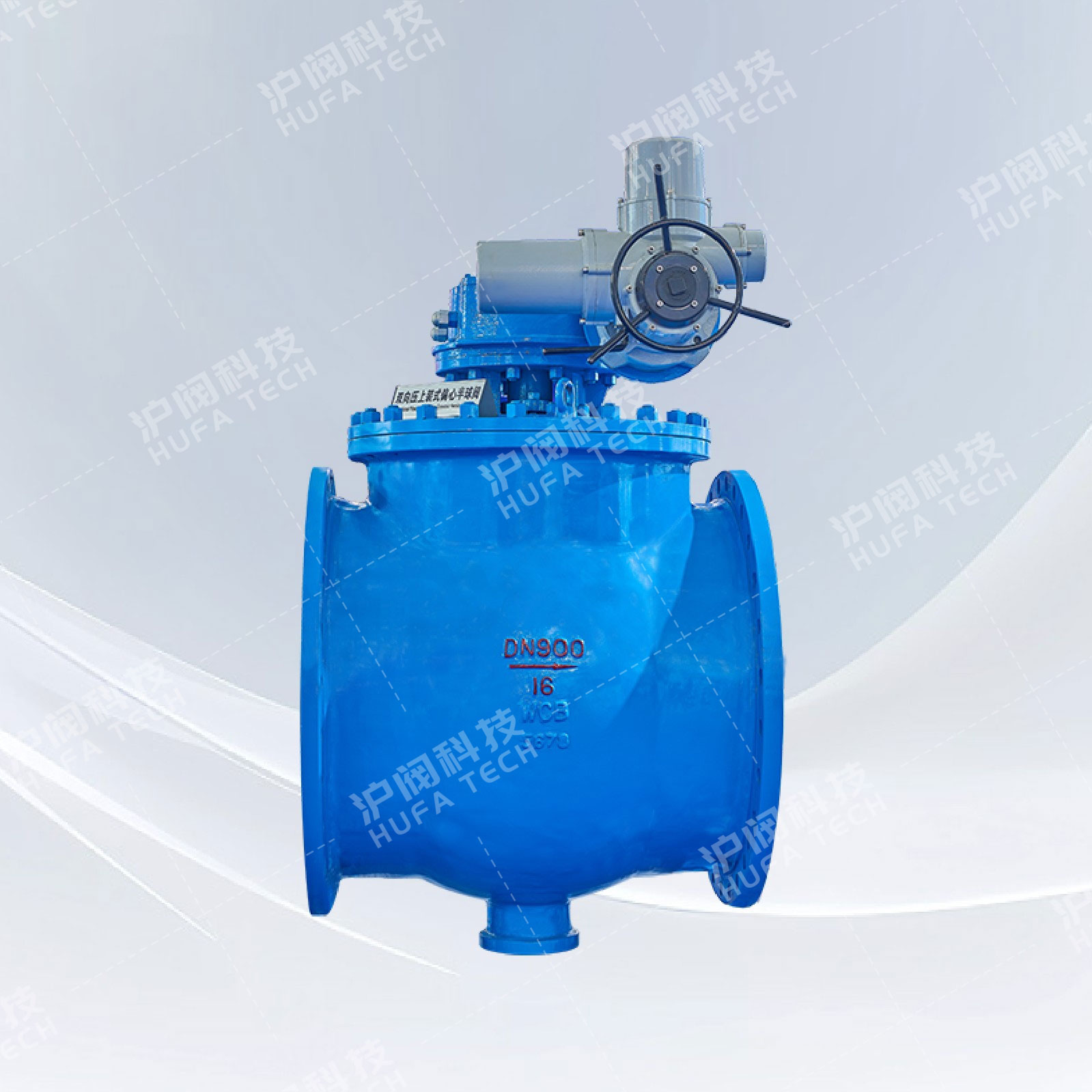
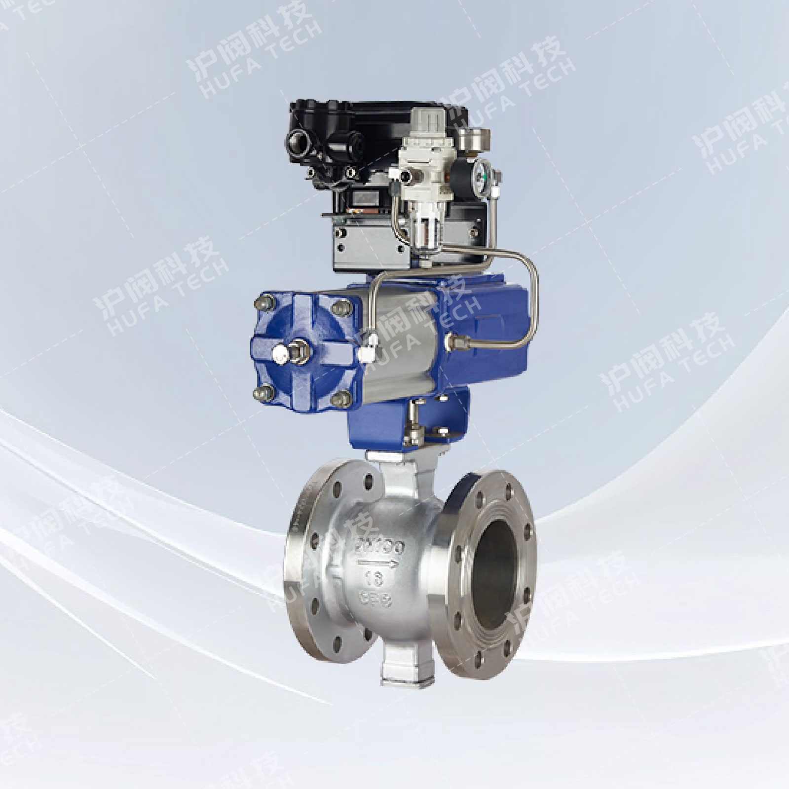
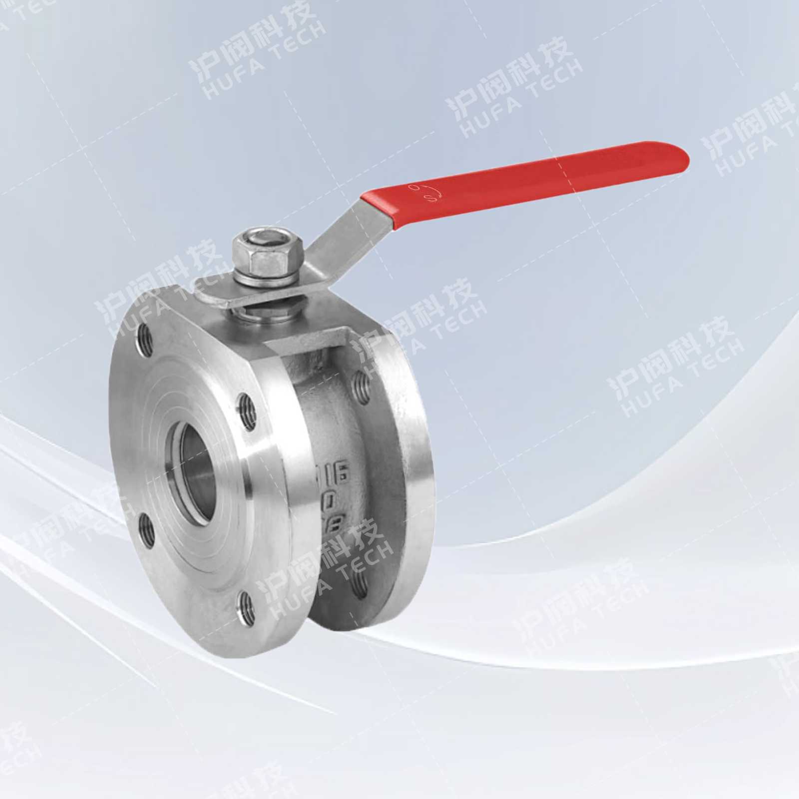
Stainless steel floating ball valve (electric)
Technical Specifications
Product model: Q941F
Nominal diameter: DN15 - 300mm
Nominal pressure: PN1.6 - 6.4 MPa
Applicable temperature range: -28℃ - 300℃
Valve body material: Stainless steel CF8
Applicable media: Steam, water, nitric acid, acetic acid
Sales Hotline:
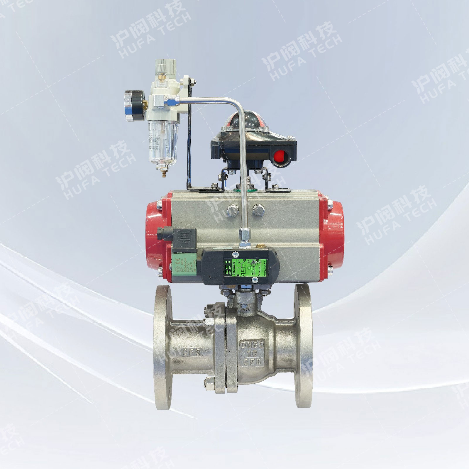
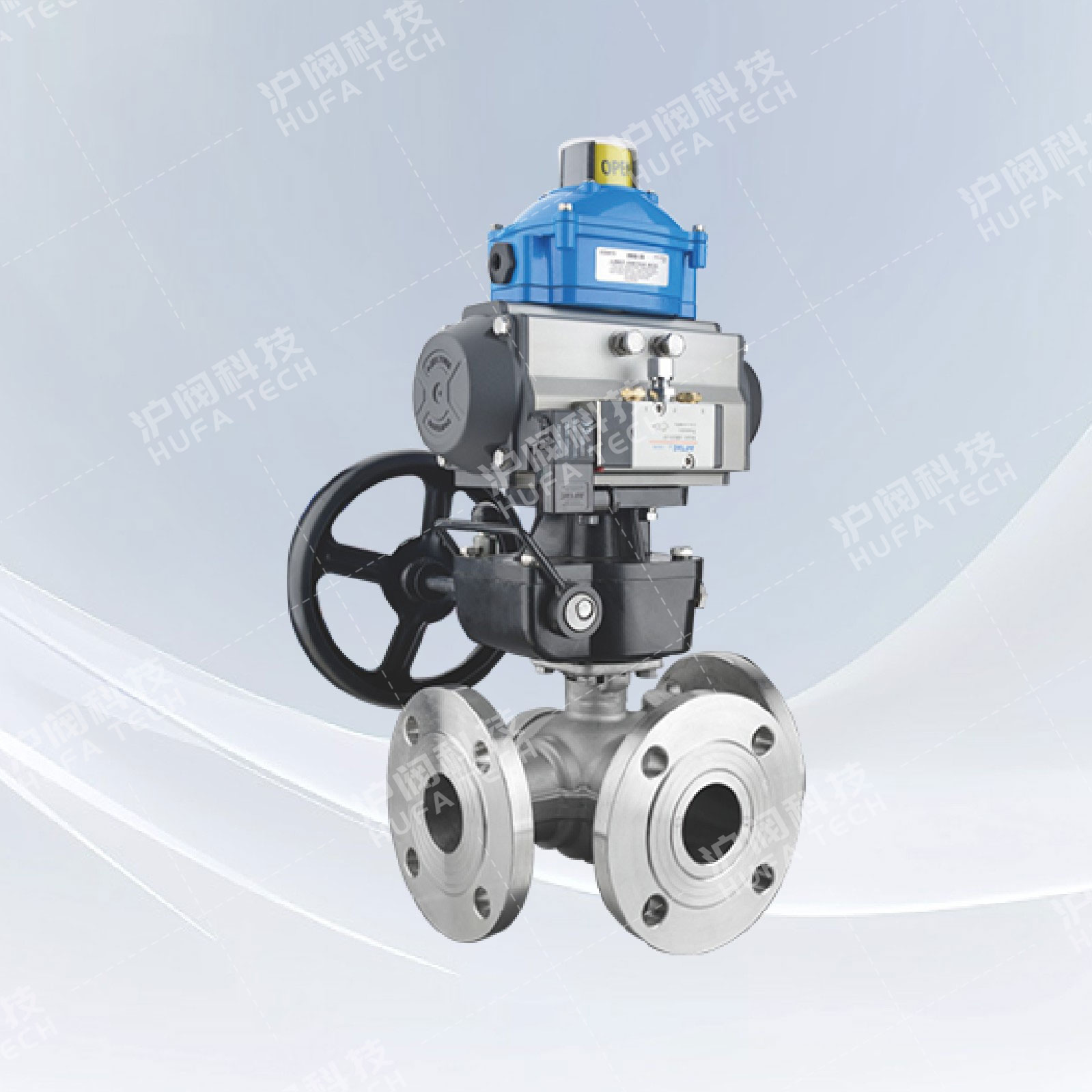
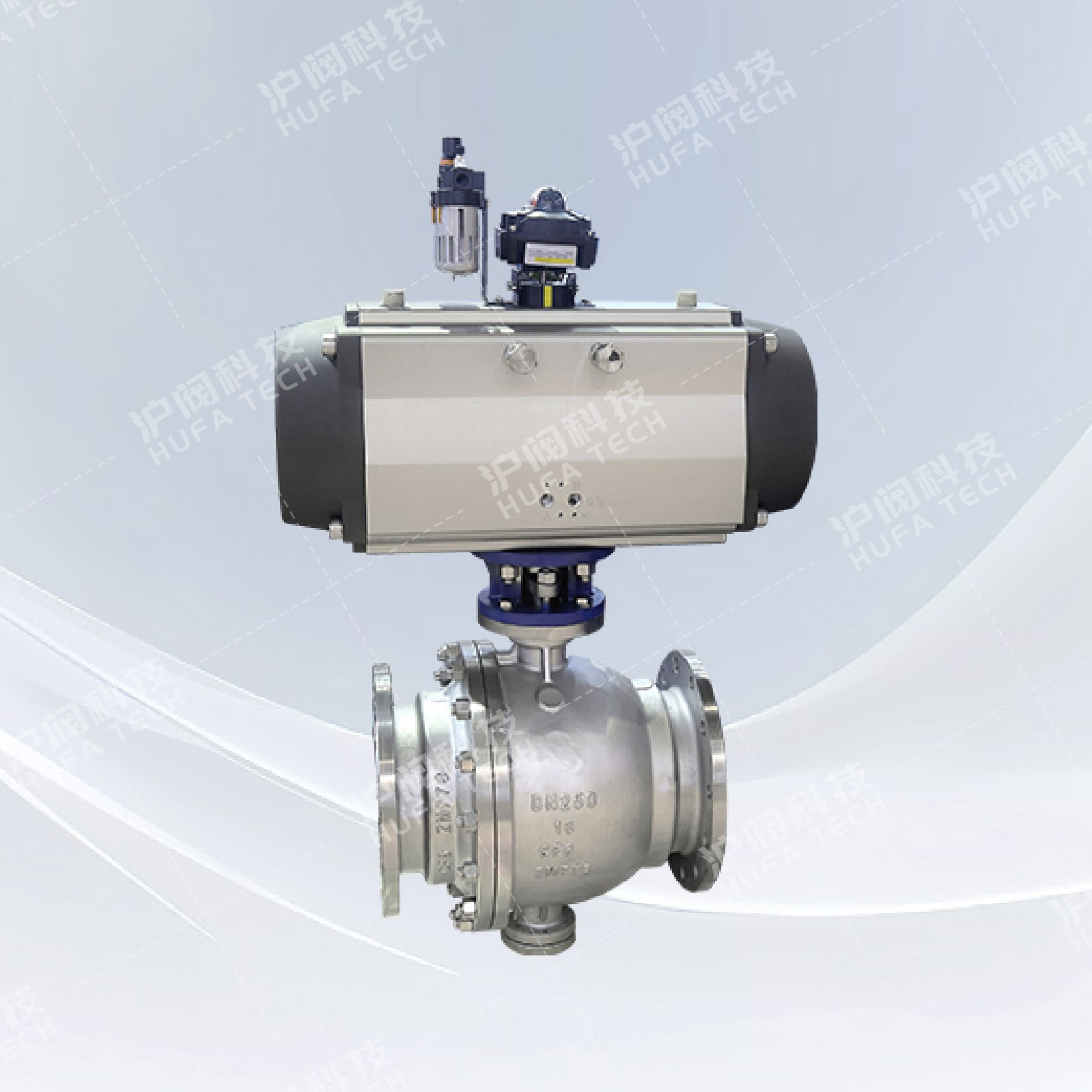
Product Details
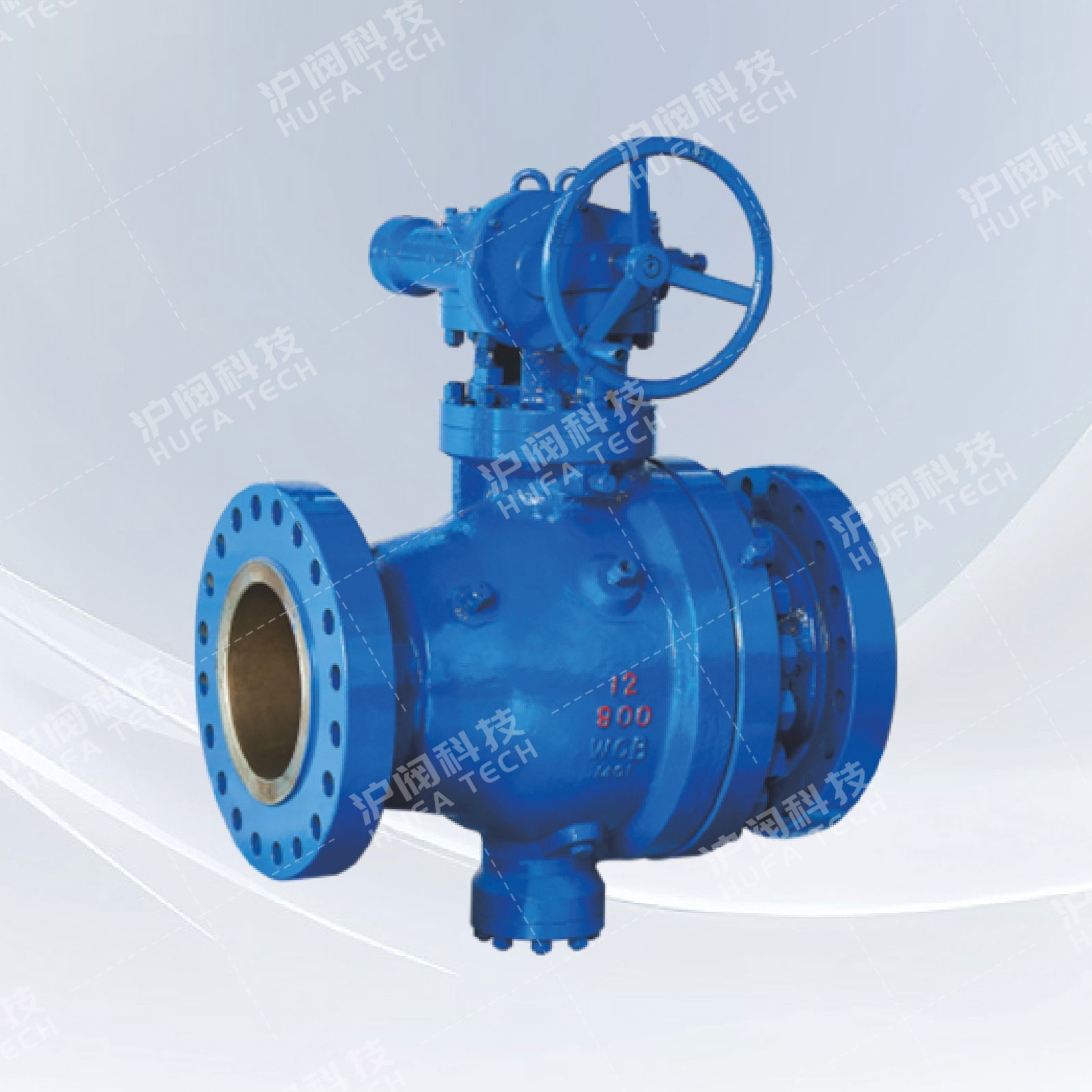
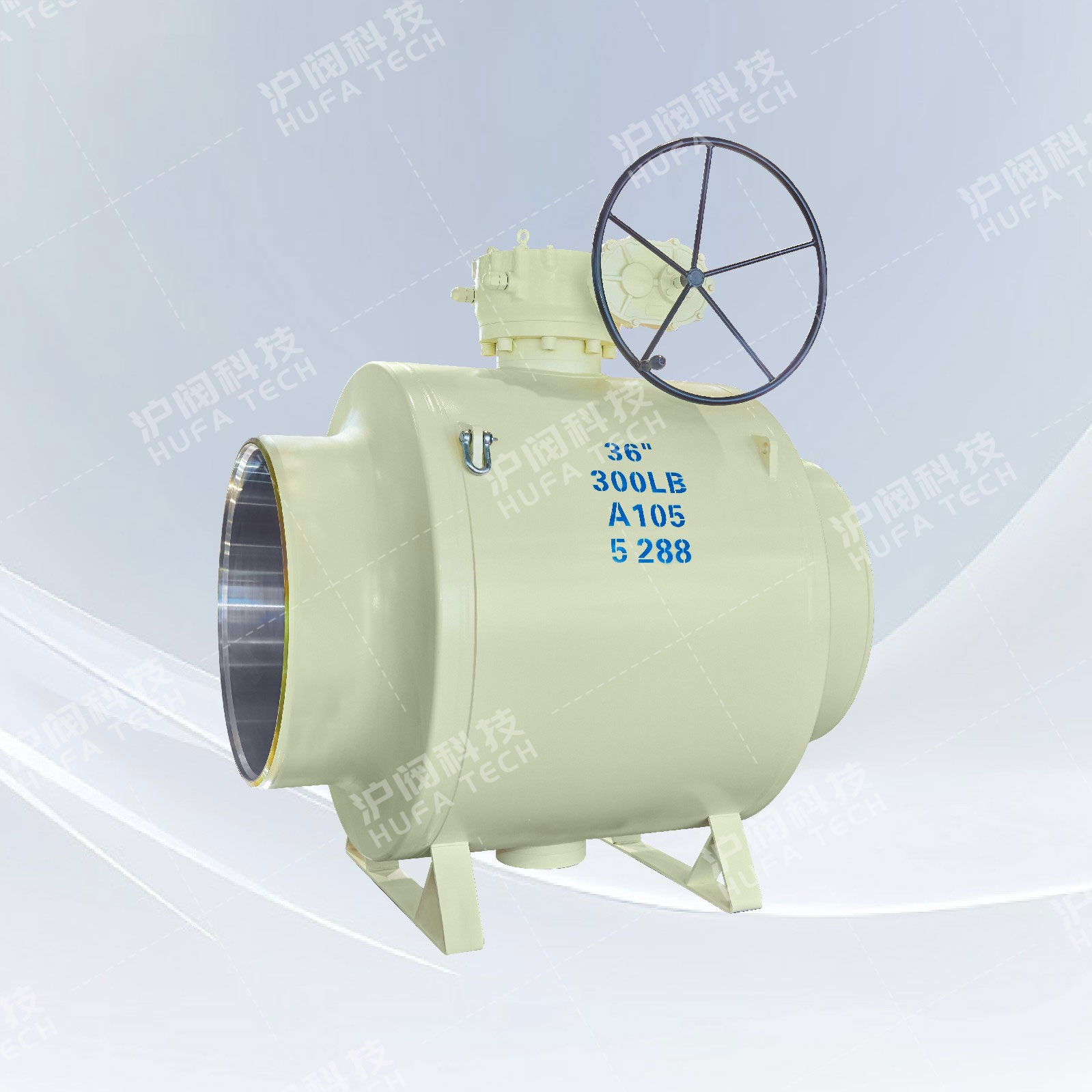
Product structural characteristics
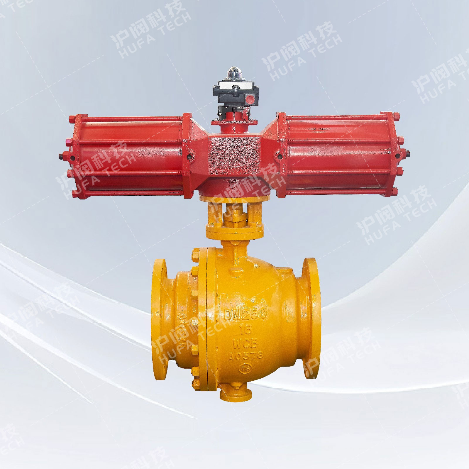
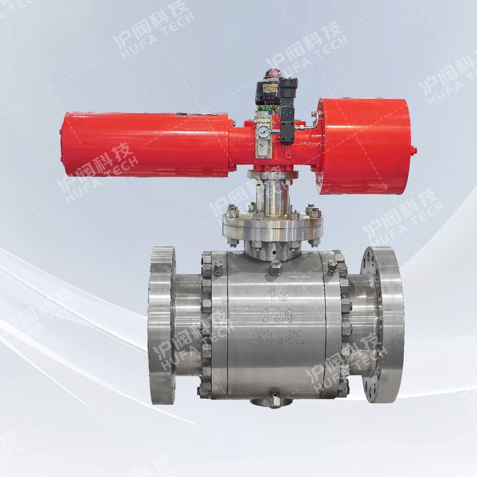
The series of floating ball valves are mainly applicable to industries such as natural gas, oil products, chemicals, metallurgy, urban construction, environmental protection, pharmaceuticals, food, etc. Among them, the anti-sulfur series is suitable for natural gas long-distance pipelines containing hydrogen sulfide, with high impurity content and severe corrosion.
Its main structural features are
The floating ball valve adopts a double inclined surface elastic sealing ring or V-shaped groove elastic sealing ring structure design to ensure the reliability of the seal. For ball valves used in low-pressure, ultra-low pressure or vacuum conditions, a valve seat sealing structure with spring loading is adopted, which can ensure the long-term reliable sealing of the ball valve. The valve seat materials of medium and high-temperature ball valves can be selected from oriented polyphenylene or metal materials.
2. Automatic pressure relief structure; When the pressure in the middle chamber abnormally rises, the medium in the middle chamber can rely on its own thrust to push the valve seat and automatically relieve the pressure, thereby ensuring the safety of the valve body.
3. Reliable sealing of the valve stem; The valve stem adopts a bottom-mounted structure with reverse sealing. The sealing force of the reverse seal increases with the increase of medium pressure, thus ensuring the reliable sealing of the valve stem. Moreover, when the valve chamber experiences abnormal pressure rise, the valve stem will not spurt out.
4. Fireproof Structure; According to the working conditions and the needs of the users, the ball valve can be designed as a fireproof structure. The fire-resistant design of the ball valve complies with the provisions of standards such as API 607, API 6FA and JB/T 6899. In the event of a fire causing the soft sealing ring to burn out, the fireproof structure of the ball valve can prevent a large amount of medium from leaking and prevent the further expansion of the fire.
5. Anti-static structure; When operating the valve, due to the friction between the ball and the valve seat, static charges will be generated and accumulate on the ball. To prevent the occurrence of static sparks, an anti-static device is specially installed on the valve to discharge the accumulated charges on the ball.
6. Locking device; Design a lockable structure at the fully open and fully closed positions of the manual ball valve. This ensures that accidental operation and unexpected vibration of the pipeline cannot cause abnormal switching phenomena. Especially in the production lines of flammable media such as petroleum and chemical substances, as well as when the valve is installed outdoors, this design shows particularly good advantages and practical effects.
7. Full-bore structure and reduced-bore structure; To meet the diverse needs of users, our ball valve products are available in both full-bore and reduced-bore series. The inner diameter of the channel in the full-bore ball valve is consistent with the inner diameter of the pipeline, facilitating management and cleaning. While the reduced-bore series ball valves are relatively lightweight in weight, and the fluid resistance is only about 1/7 of that of the same-sized stop valve, thus the application prospects of the reduced-bore series ball valves are more promising.
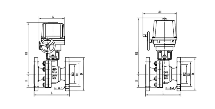
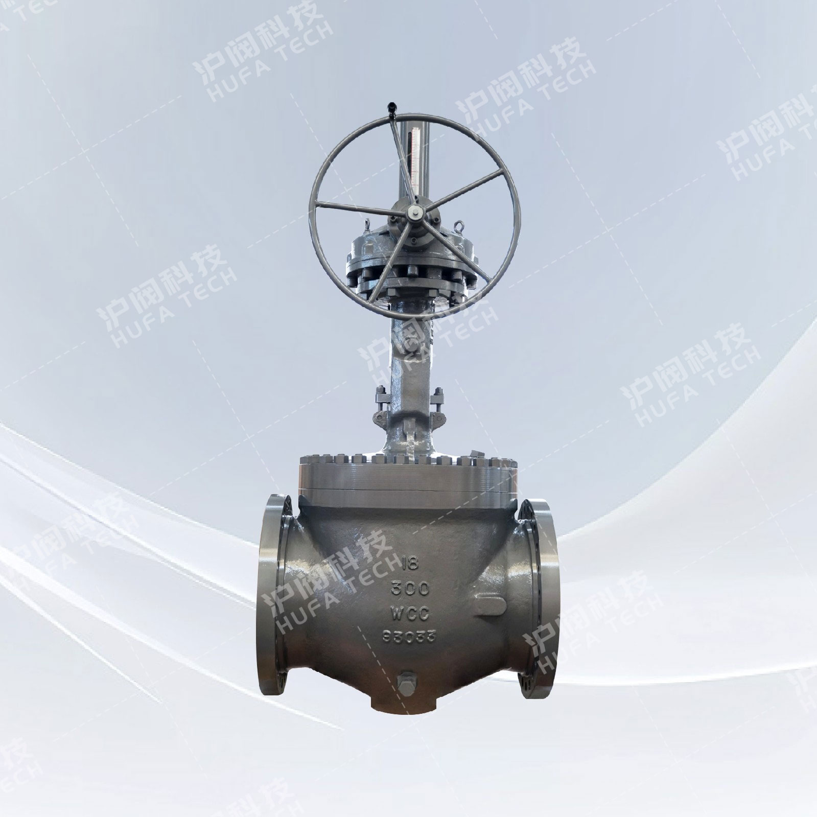
Main dimensions of the shape
|
DN(mm) |
15 |
20 |
25 |
32 |
40 |
50 |
65 |
80 |
100 |
125 |
150 |
200 |
250 |
300 |
|
L |
130 |
140 |
150 |
165 |
180 |
200 |
220 |
250 |
280 |
320 |
360 |
400 |
630 |
750 |
|
H |
44.5 |
49 |
55 |
65 |
65 |
75 |
90 |
95 |
115 |
127 |
140 |
172.5 |
310 |
350 |
|
H1 |
It depends on the model of the actuator that is equipped. |
|||||||||||||
|
D |
95 |
105 |
115 |
140 |
150 |
165 |
185 |
200 |
220 |
250 |
285 |
340 |
405 |
460 |
|
D1 |
65 |
75 |
85 |
100 |
110 |
125 |
145 |
160 |
180 |
210 |
240 |
295 |
355 |
410 |
|
D2 |
46 |
56 |
65 |
76 |
84 |
99 |
118 |
132 |
156 |
184 |
211 |
266 |
319 |
370 |
|
n-φd |
4-14 |
4-14 |
4-14 |
4-18 |
4-18 |
4-18 |
4-18 |
8-18 |
8-18 |
8-18 |
8-22 |
12-22 |
12-26 |
12-26 |
|
A、A1 |
The size will vary depending on the torque required by the valve and the type of machine it is configured for. |
|||||||||||||
 Check the mobile website