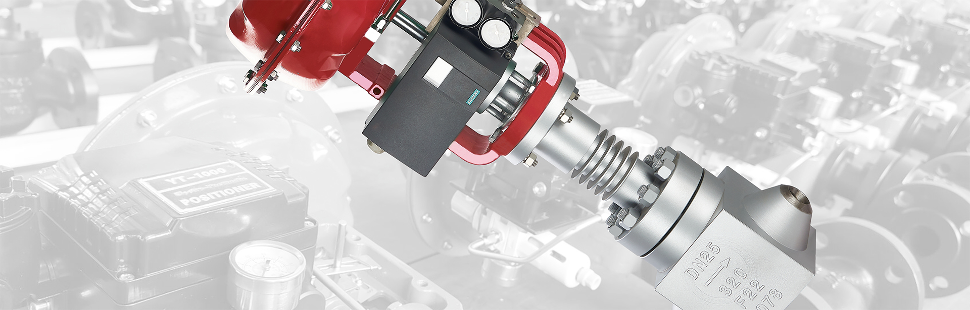
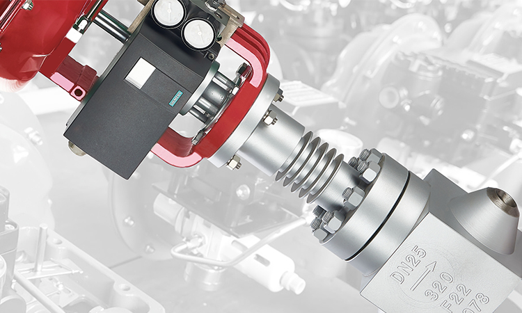

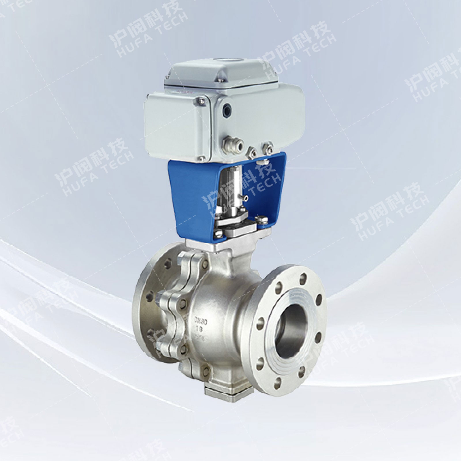
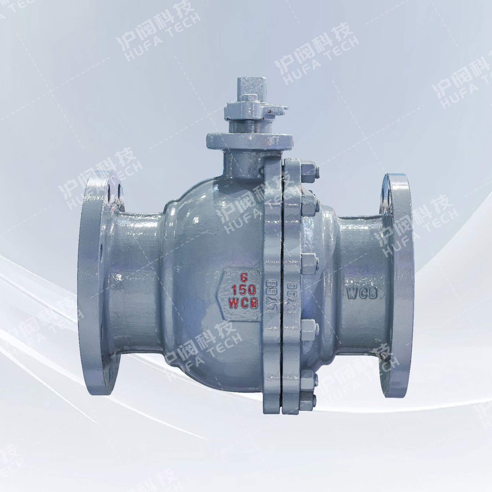
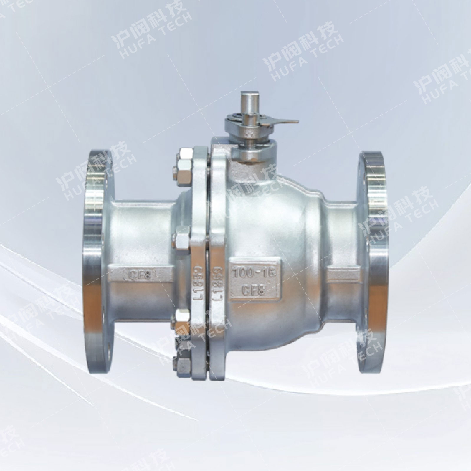
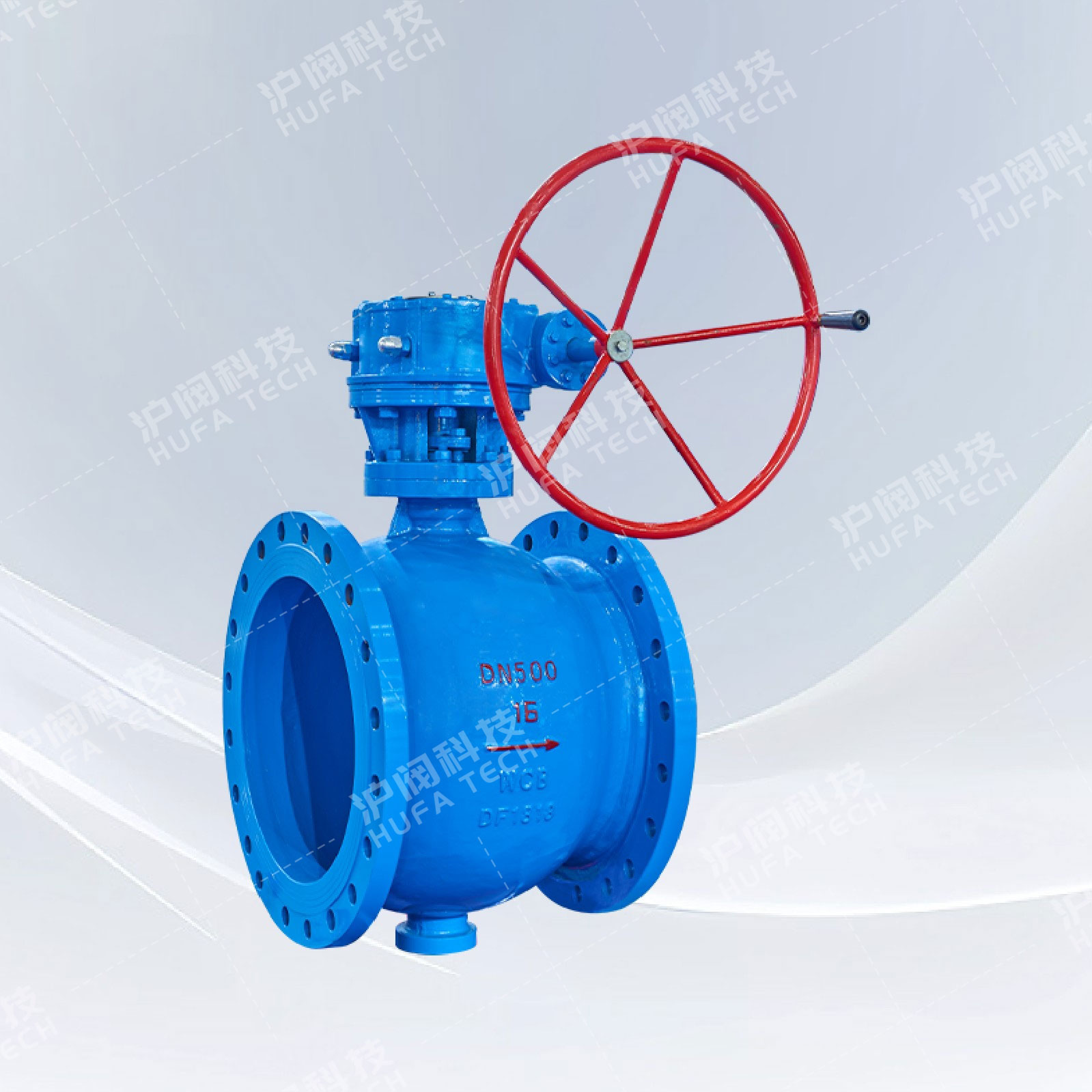
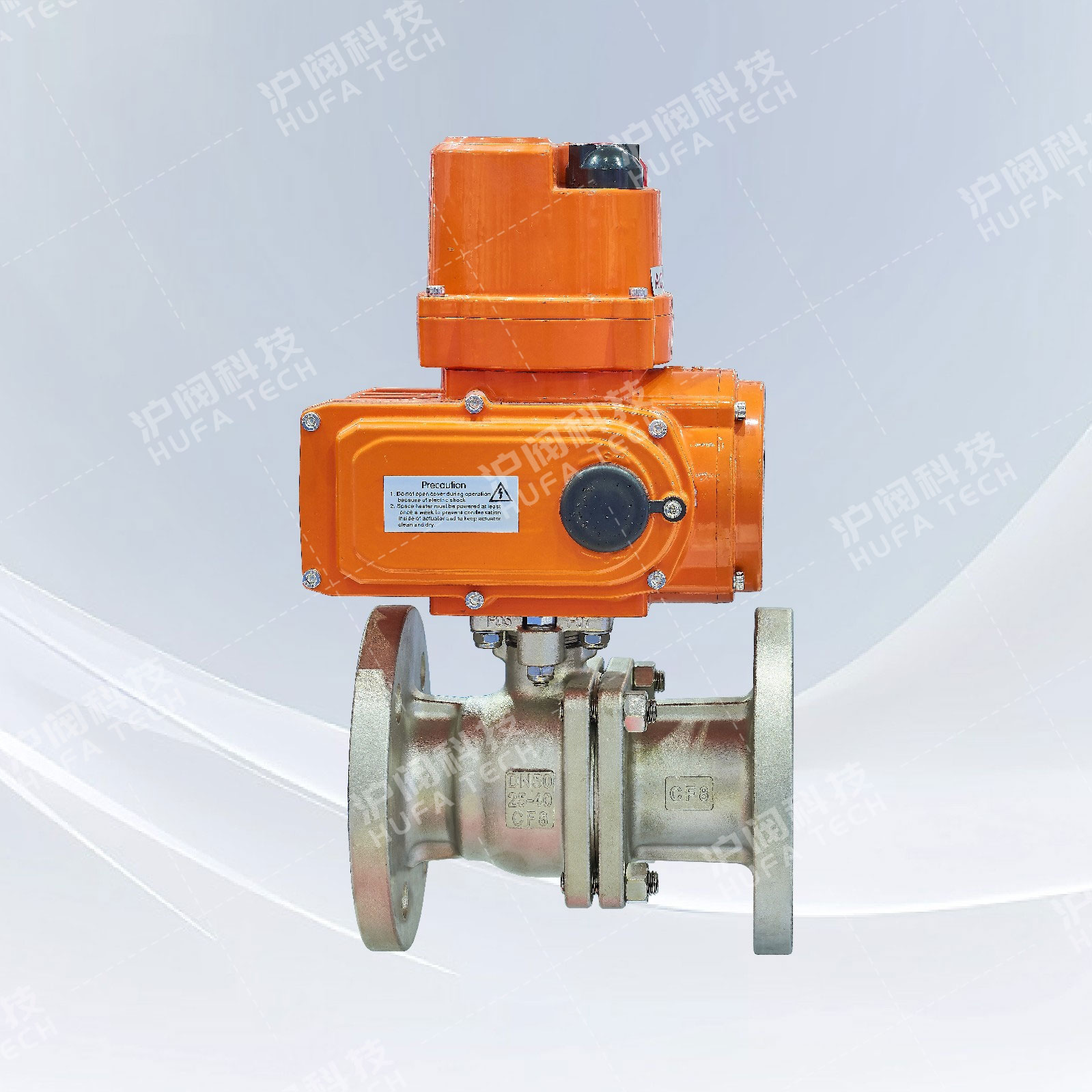
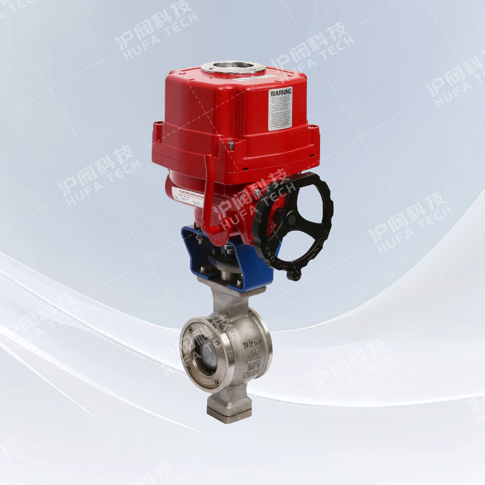
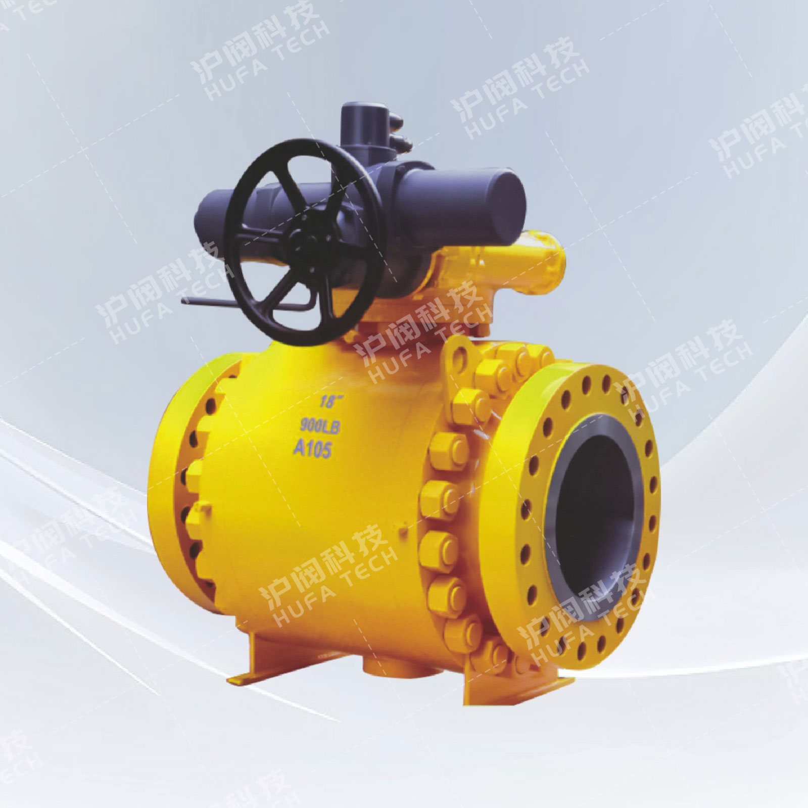
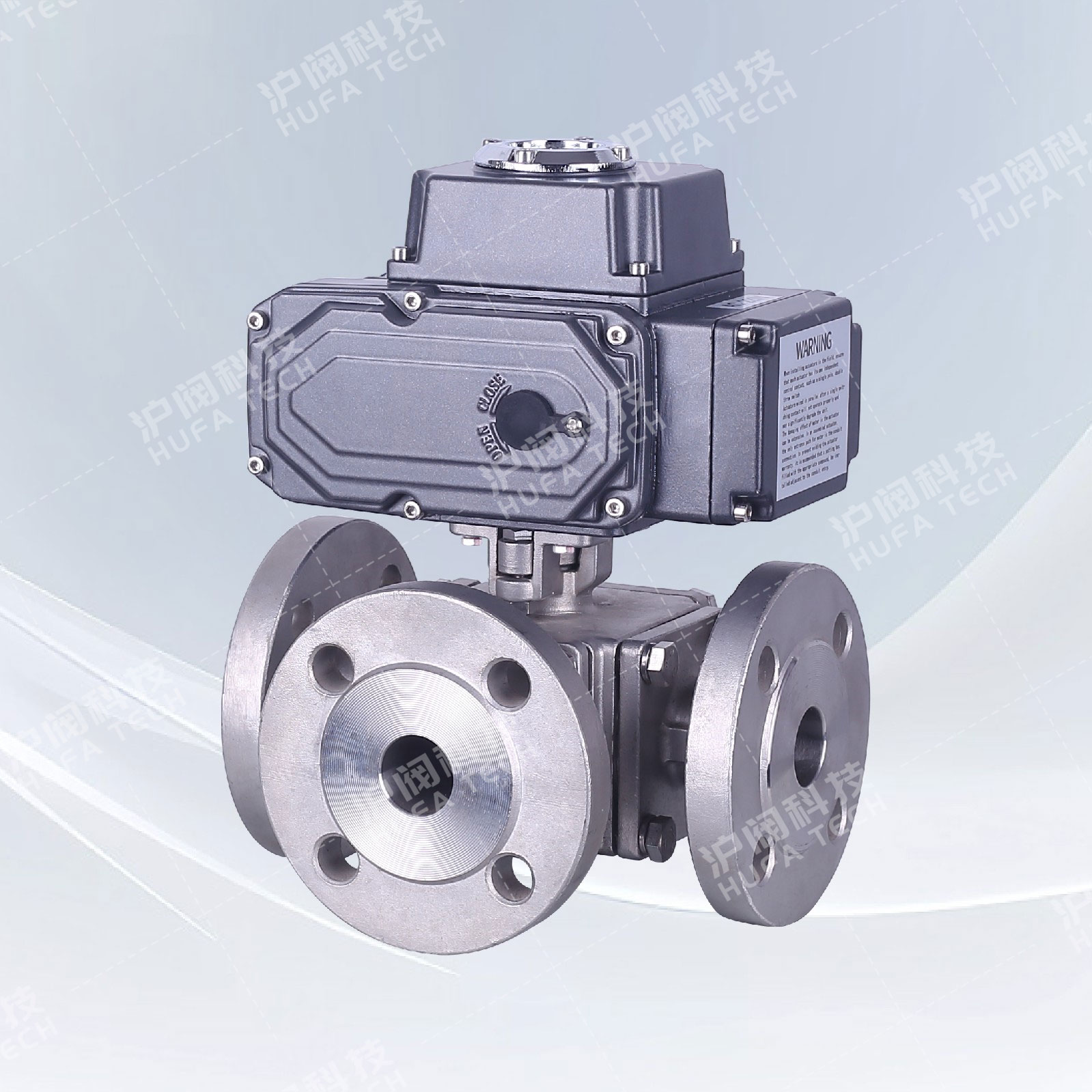
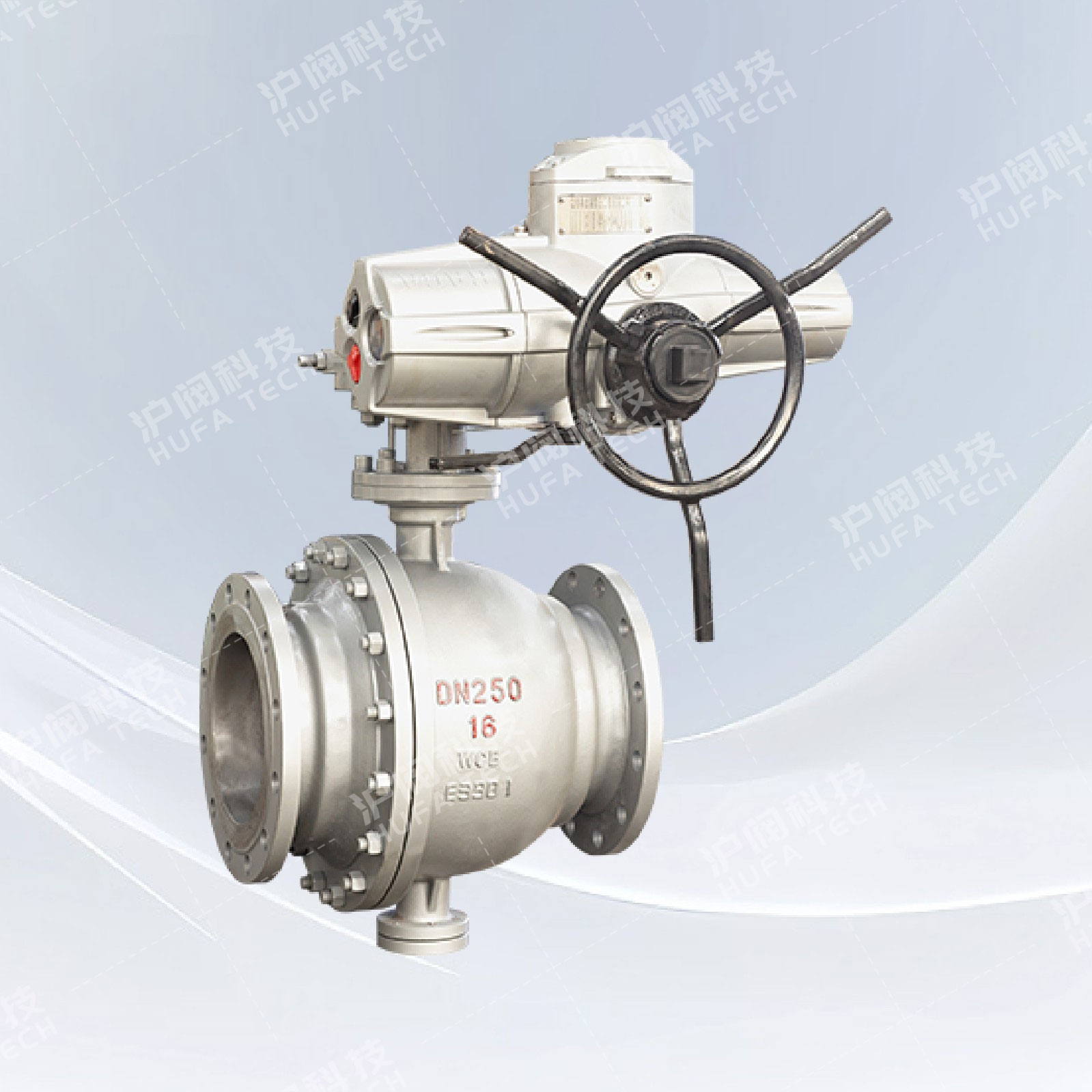
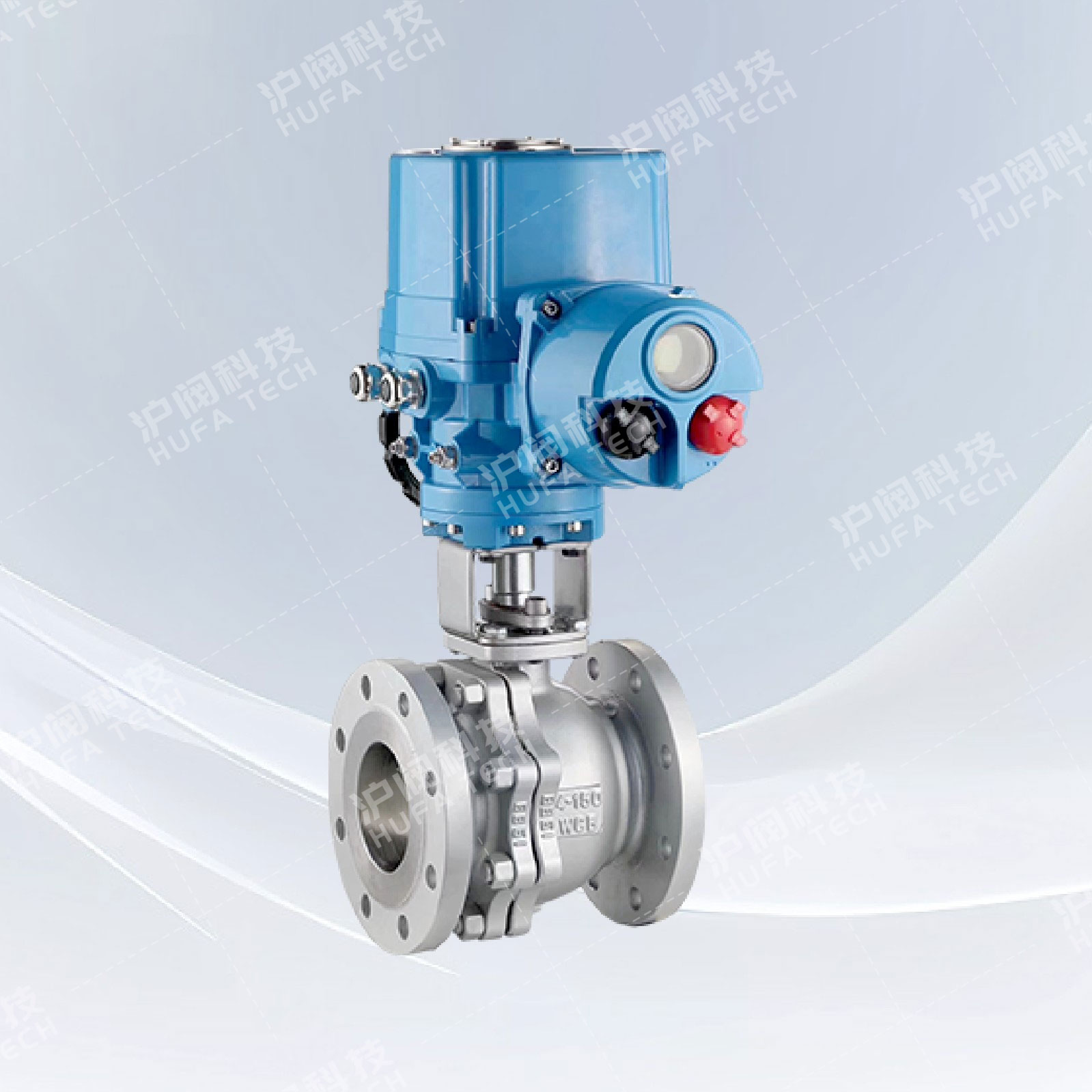
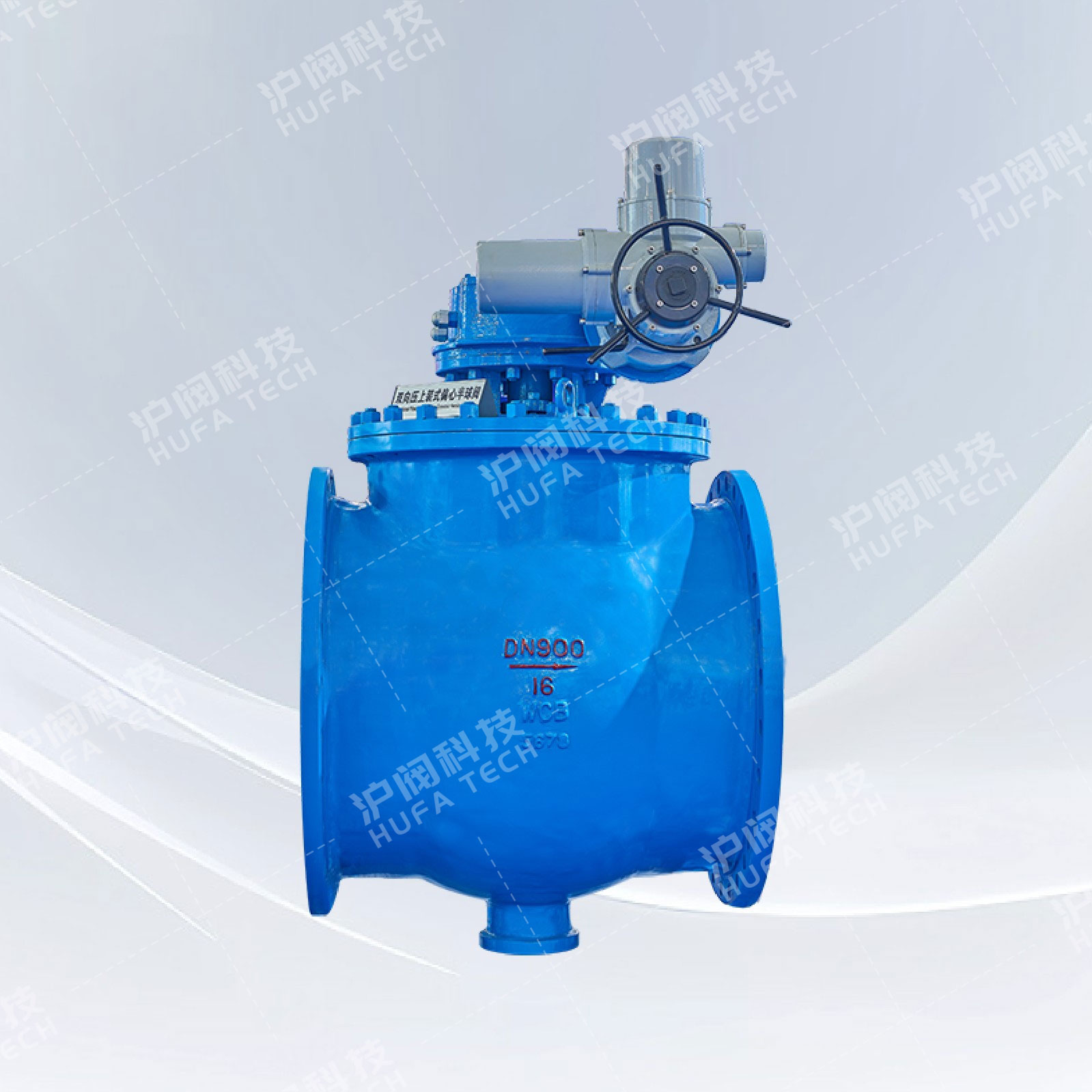
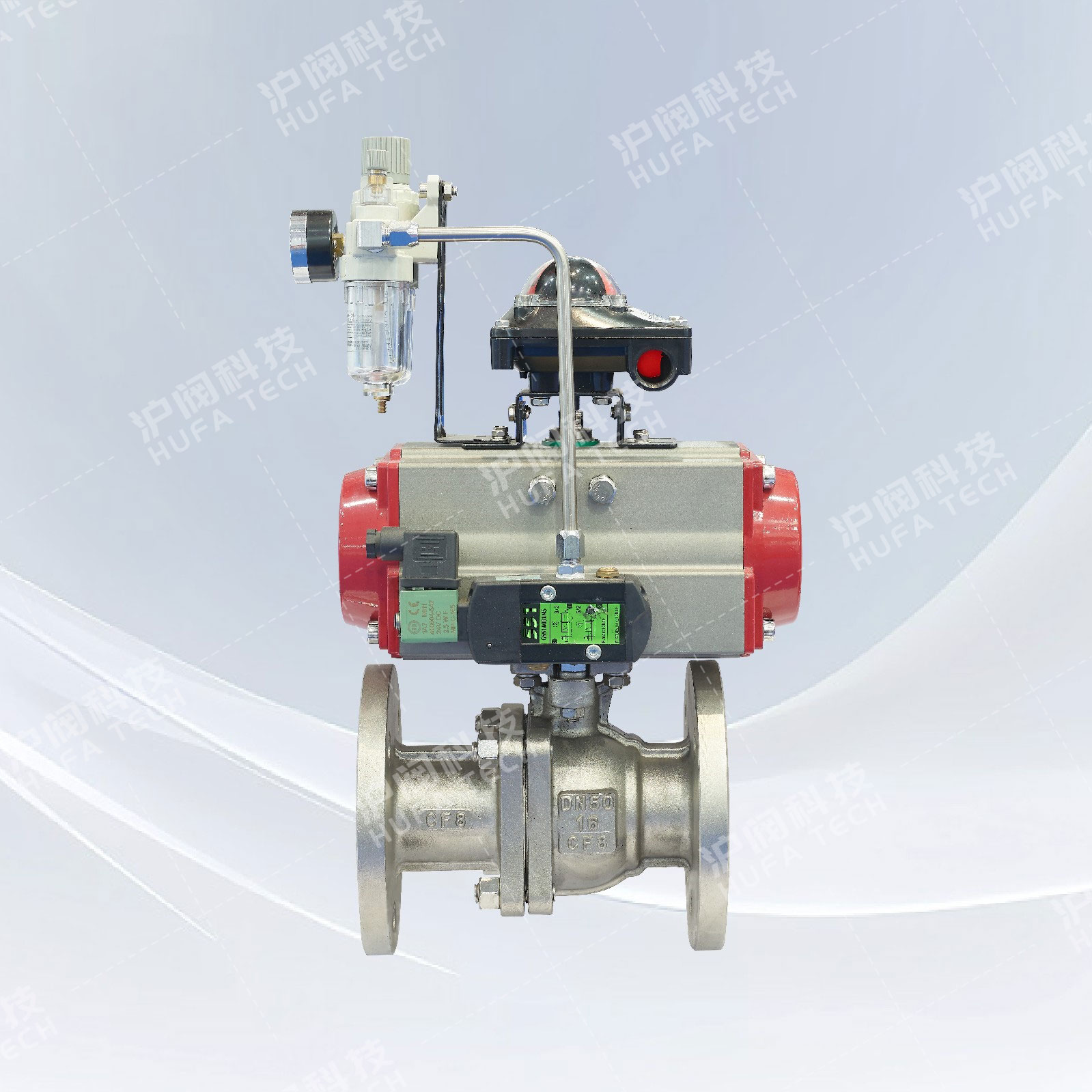
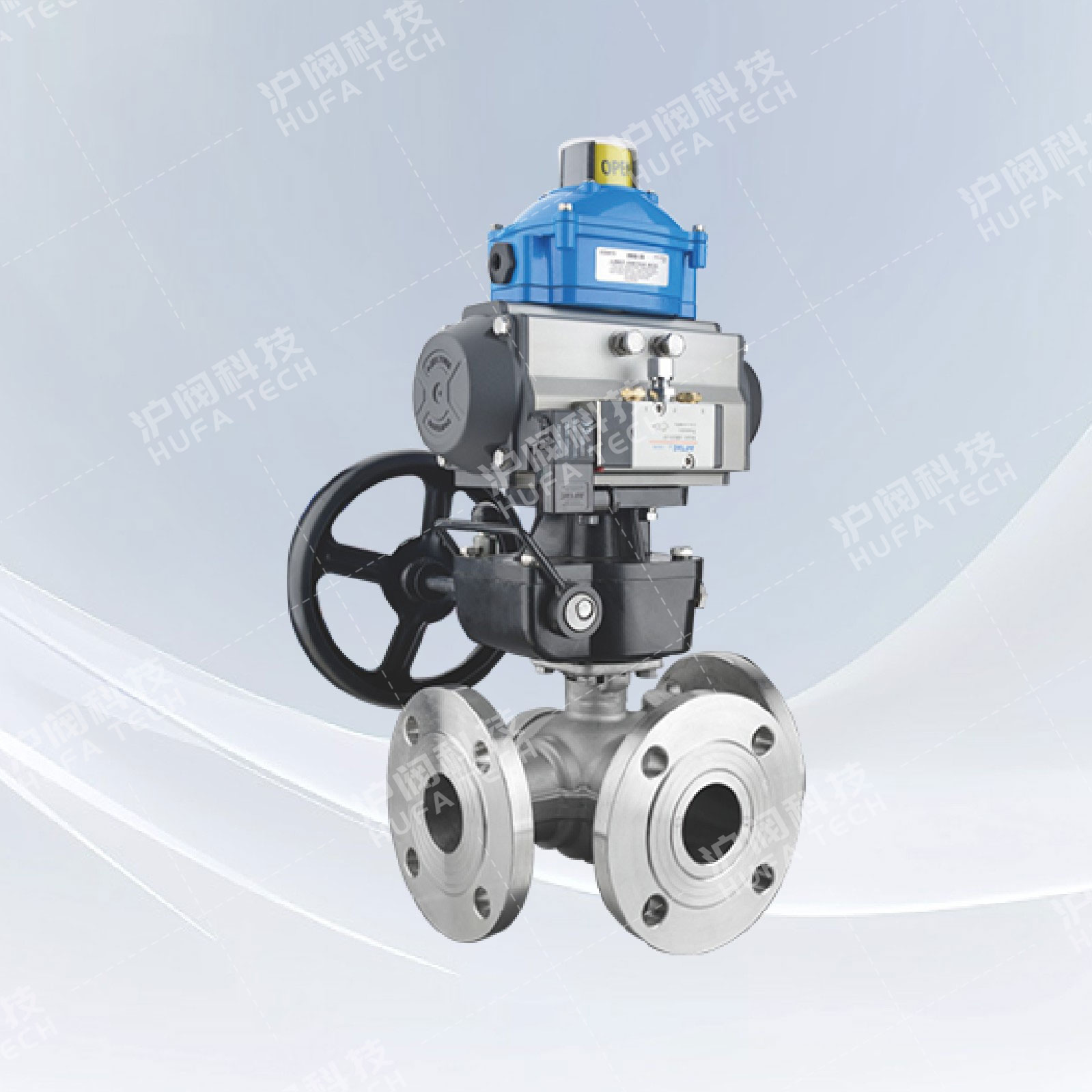
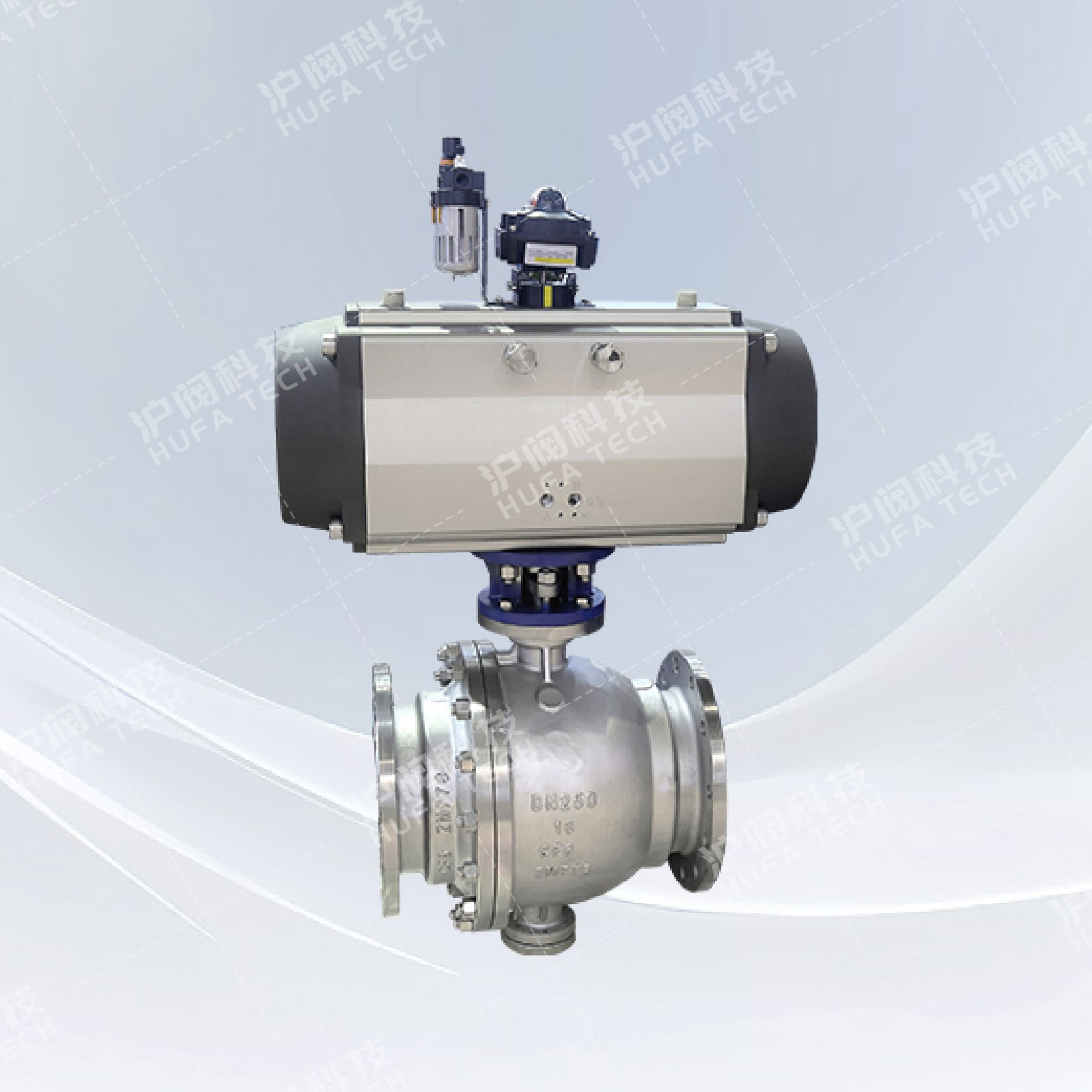
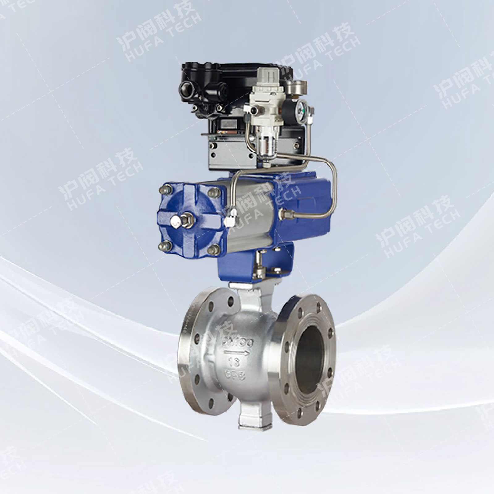
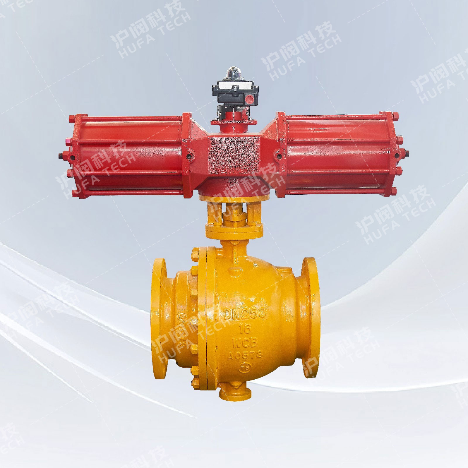
Electric O-type cut-off ball valve
Technical Specifications
Valve model: Q947F/H
Nominal diameter: DN25 - 300mm
Pressure range: 1.6 - 4.0 MPa
Operating temperature: -29℃ to 200℃
Applicable media: syrup, fibers, granules, pulp
European standard: GB/T9113-2010
Structural form: Floating ball valve
Valve material: Stainless steel CF8
Drive mode: Electric, Intelligent, Adjustable
Sales Hotline:
Product Details
Product Overview
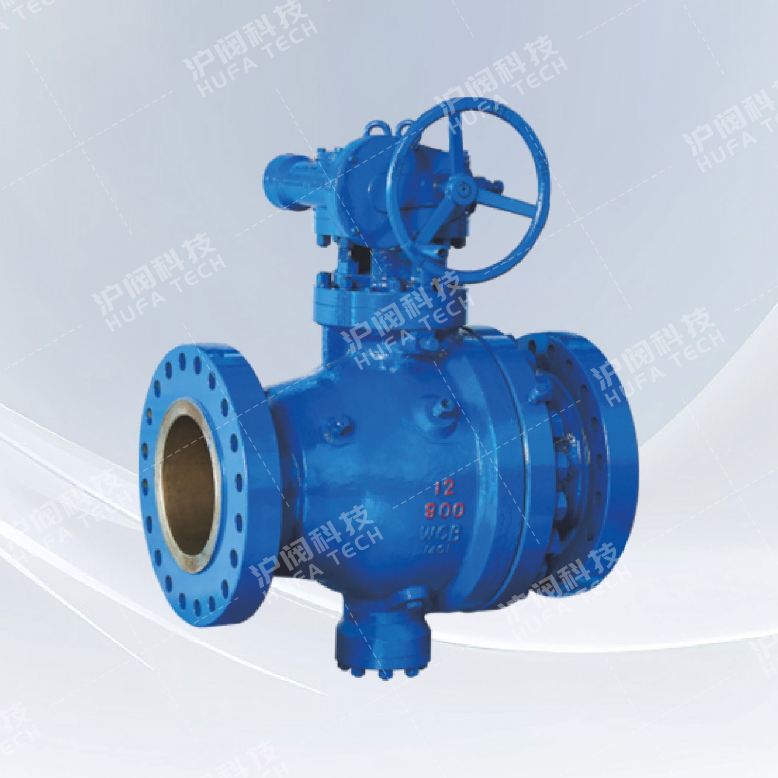
The electric O-type cut-off ball valve is a commonly used cutting-type valve in modern industrial conveying pipelines. It is composed of an intelligent electric actuator and an O-type ball valve, with the ball core being an O-type through-hole. During operation, the ball center and the sealing ring rotate without any gap. When the O-type ball core is closed, it has excellent cutting force. It is particularly suitable for pipelines transporting syrup, fibers, particles, pulp, and some viscous media. The working principle is to complete the cutting and regulation of the ball valve by using a (220V, 380V) power supply voltage as the driving force and accepting (4-20mA) industrial signals to drive the valve stem to rotate (0-90°) to change the opening degree. It is usually suitable for occasions with strict sealing requirements and is widely used in automatic control in industries such as chemical engineering, petroleum, pharmaceuticals, and light industry.
Product features
1. The electric cut-off ball valve operates with great speed and accuracy, enabling quick completion of the opening and closing actions.
2. The operation is very convenient. From fully open to fully closed, it only requires a 90-degree rotation, making it easy to control from a distance.
3. It has a large flow capacity and, when fully open, there is virtually no flow resistance.
4. The electric O-type cut-off ball valve has wide applicability. Different connection methods and various types of sealing rings can be selected to meet different operating conditions.
5. It has excellent self-cleaning capabilities, which can easily remove various impurities from the pipeline and effectively ensure the smooth flow of the pipeline.
Main technical parameters
| DN | DN25~DN300(mm) | ||
| PN | PN1.0、1.6、2.5、6.4MPa | ||
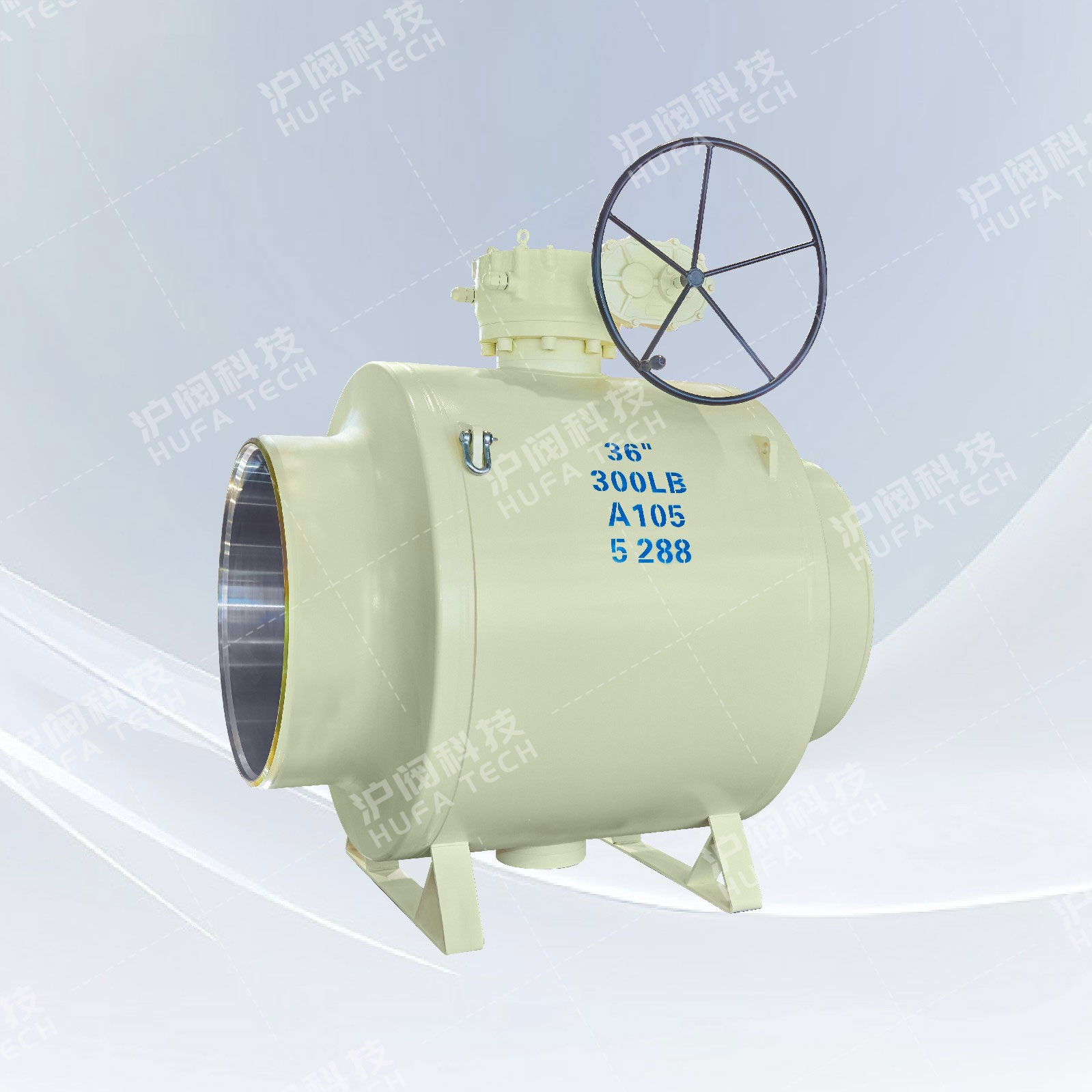
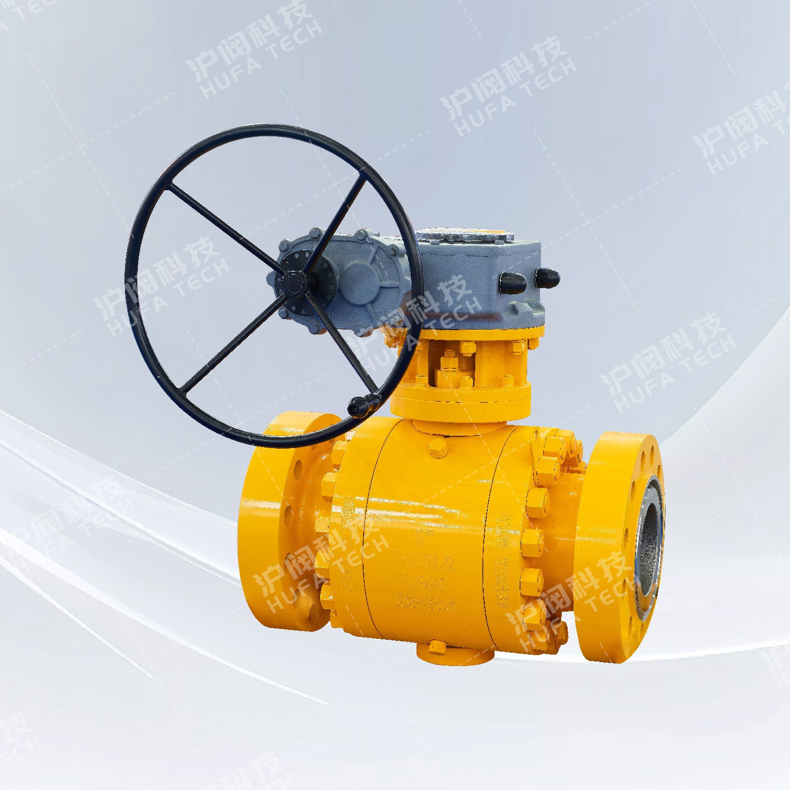
| Connection form | Flange | ||
| Drive form | Power supply drive (optional explosion-proof type, with built-in manual device) | ||
| Power supply voltage | AC220V、AC380V(Other customized DC24) | ||
| Valve core type | O-type ball-shaped valve core | ||
| Leakage rate | Soft seal: Zero leakage. Hard seal: ≤ 10^-5 of the rated flow rate. | ||
| Action time | 8~30(DN15-50) 36~60(DN65-300)Customizable | ||
| Valve body material | Carbon steel, stainless steel304、316、316L | ||
| Flow characteristics | Approximate quick-opening characteristic | ||
| Applicable temperature | Soft seal - -40℃ to -180℃; Hard seal - -40℃ to -450℃ | ||
| Control method | Switch type (two-position switch cut-off), passive contact signal, potentiometer feedback | ||
Main component materials
| Part Name | Materials | |||
| Body Bonnet | WCB | 304(CF8) | 316(CF8M) | 316L(CF3M) |
| Ball | 2Cr13+Nitriding treatment | 304 | 316 | 316L |
| Stem | 2Cr13 | 304 | 316 | 316L |
| Sealing ring | Polytetrafluoroethylene (PTFE), reinforced polytetrafluoroethylene (PPL), isotactic polypropylene, flexible graphite | |||
| Applicable medium | Liquids, gases, vapors, oil products and other corrosive media, etc. | |||
Main connection dimensions
| DN(mm) | 25 | 32 | 40 | 50 | 65 | 80 | 100 | 125 | 150 | 200 | 250 | 300 | |
| L | 150 | 165 | 180 | 200 | 220 | 250 | 280 | 320 | 360 | 400 | 630 | 750 | |
| H | Recruit HR | 287 | 312 | 312 | 325 | 335 | 365 | 400 | 420 | 440 | 470 | 545 | 580 |
| Recruit 361R | 380 | 392 | 392 | 415 | 425 | 445 | 490 | 510 | 530 | 560 | 635 | 670 | |
| W | 157 | 157 | 208 | 208 | 256 | 256 | 256 | 256 | 256 | 256 | 380 | 380 | |
| PN1.6MPa Flange connection dimensions | |||||||||||||
| D | 115 | 140 | 150 | 165 | 185 | 200 | 220 | 250 | 285 | 340 | 405 | 460 | |
| D1 | 85 | 100 | 110 | 125 | 145 | 160 | 180 | 210 | 240 | 295 | 355 | 410 | |
| D2 | 65 | 76 | 84 | 99 | 118 | 132 | 156 | 184 | 211 | 266 | 319 | 370 | |
| n-φd | 4-14 | 4-18 | 4-18 | 4-18 | 4-18 | 8-18 | 8-18 | 8-18 | 8-22 | 12-22 | 12-26 | 12-26 | |
| PN2.5MPa Flange connection dimensions | |||||||||||||
| D | 115 | 140 | 150 | 165 | 185 | 200 | 235 | 270 | 300 | 360 | 425 | 485 | |
| D1 | 85 | 100 | 110 | 125 | 145 | 160 | 190 | 220 | 250 | 310 | 370 | 430 | |
| D2 | 65 | 76 | 84 | 99 | 118 | 132 | 156 | 184 | 211 | 274 | 330 | 389 | |
| n-φd | 4-14 | 4-18 | 4-18 | 4-18 | 8-18 | 8-18 | 8-22 | 8-26 | 8-26 | 12-26 | 12-30 | 16-30 | |
| PN4.0MPa Flange connection dimensions | |||||||||||||
| D | 115 | 140 | 150 | 165 | 185 | 200 | 235 | 270 | 300 | 375 | 450 | 515 | |
| D1 | 85 | 100 | 110 | 125 | 145 | 160 | 190 | 220 | 250 | 320 | 385 | 450 | |
| D6 | 58 | 66 | 76 | 88 | 110 | 121 | 150 | 176 | 204 | 260 | 313 | 364 | |
| n-φd | 4-14 | 4-18 | 4-18 | 4-18 | 8-18 | 8-18 | 8-22 | 8-26 | 8-26 | 12-30 | 12-22 | 16-33 | |
| PN6.3MPa Flange connection dimensions | |||||||||||||
| D | 140 | 155 | 170 | 180 | 205 | 215 | 250 | 295 | 345 | 415 | 470 | 530 | |
| D1 | 100 | 110 | 125 | 135 | 160 | 170 | 200 | 240 | 280 | 345 | 400 | 460 | |
| D6 | 58 | 66 | 76 | 88 | 110 | 121 | 150 | 176 | 204 | 260 | 313 | 364 | |
| n-φd | 4-18 | 4-22 | 4-22 | 4-22 | 8-22 | 8-22 | 8-26 | 8-30 | 8-33 | 12-36 | 12-36 | 16-36 | |
 Check the mobile website