
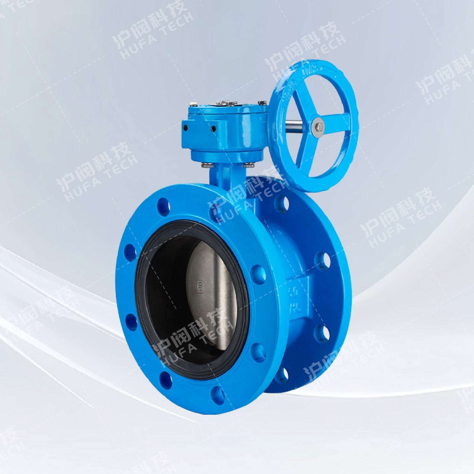
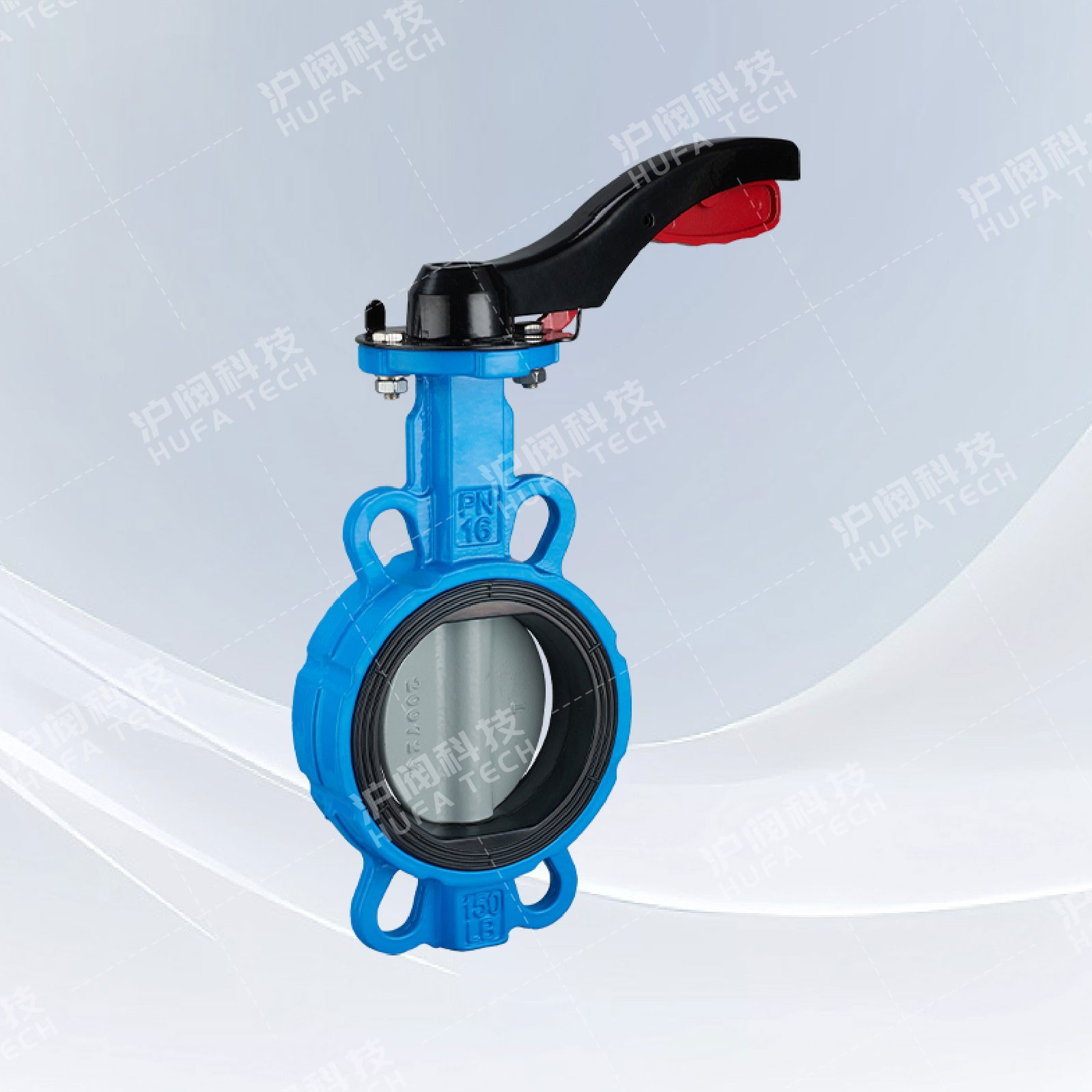
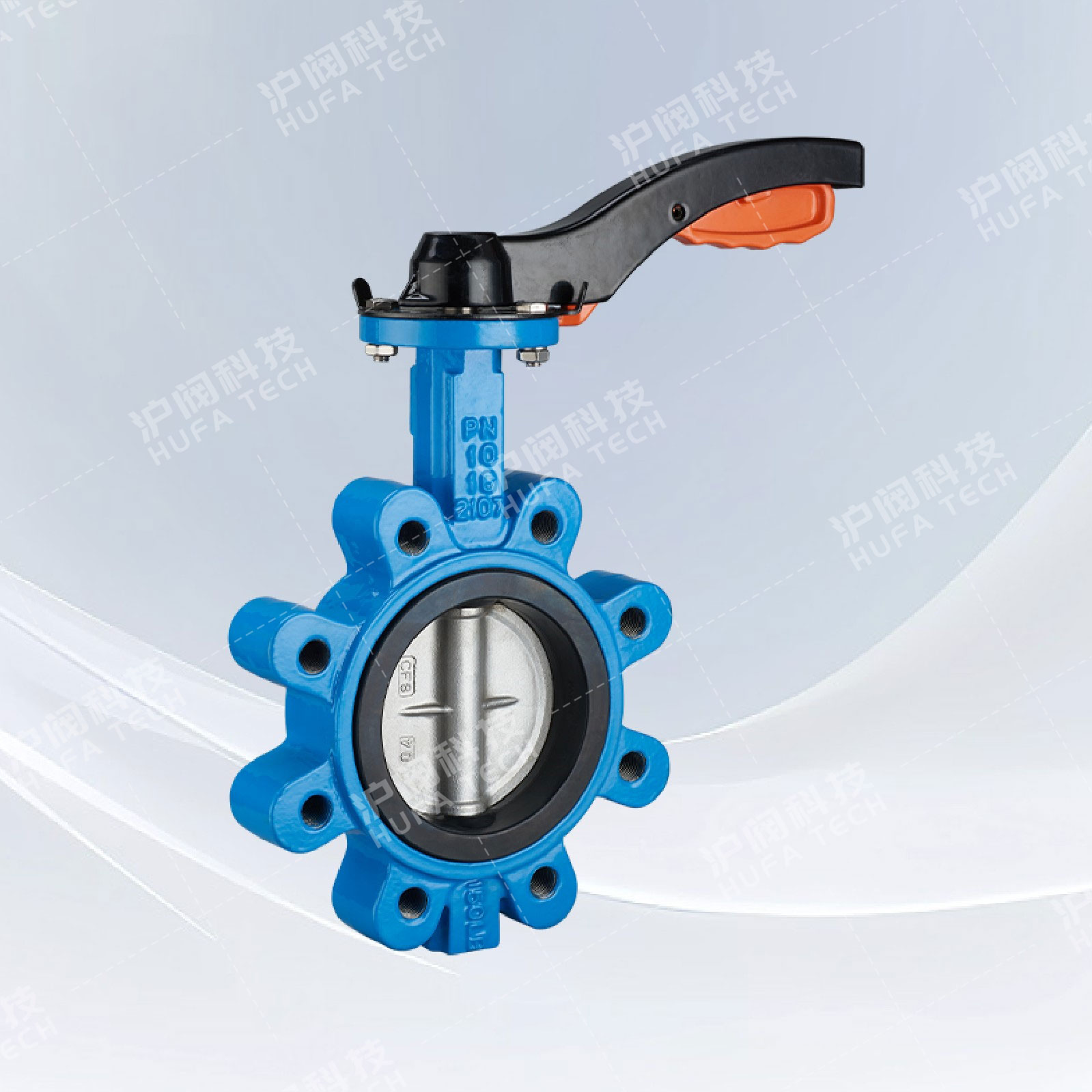
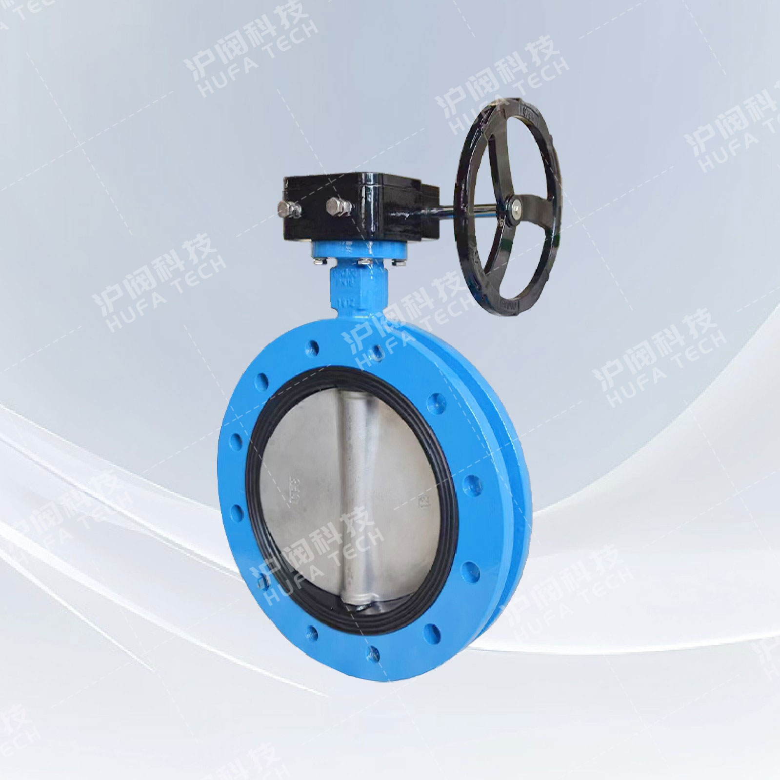
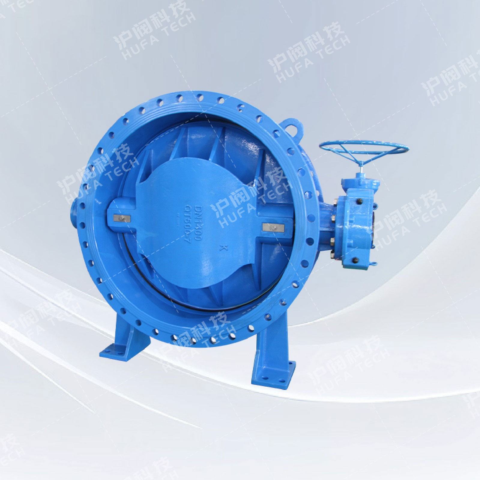
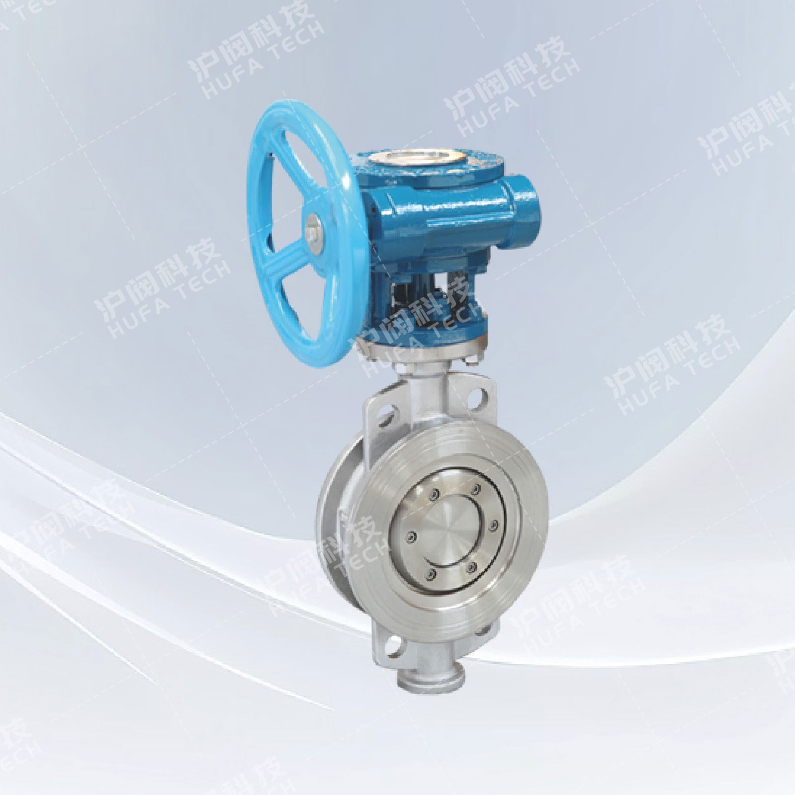
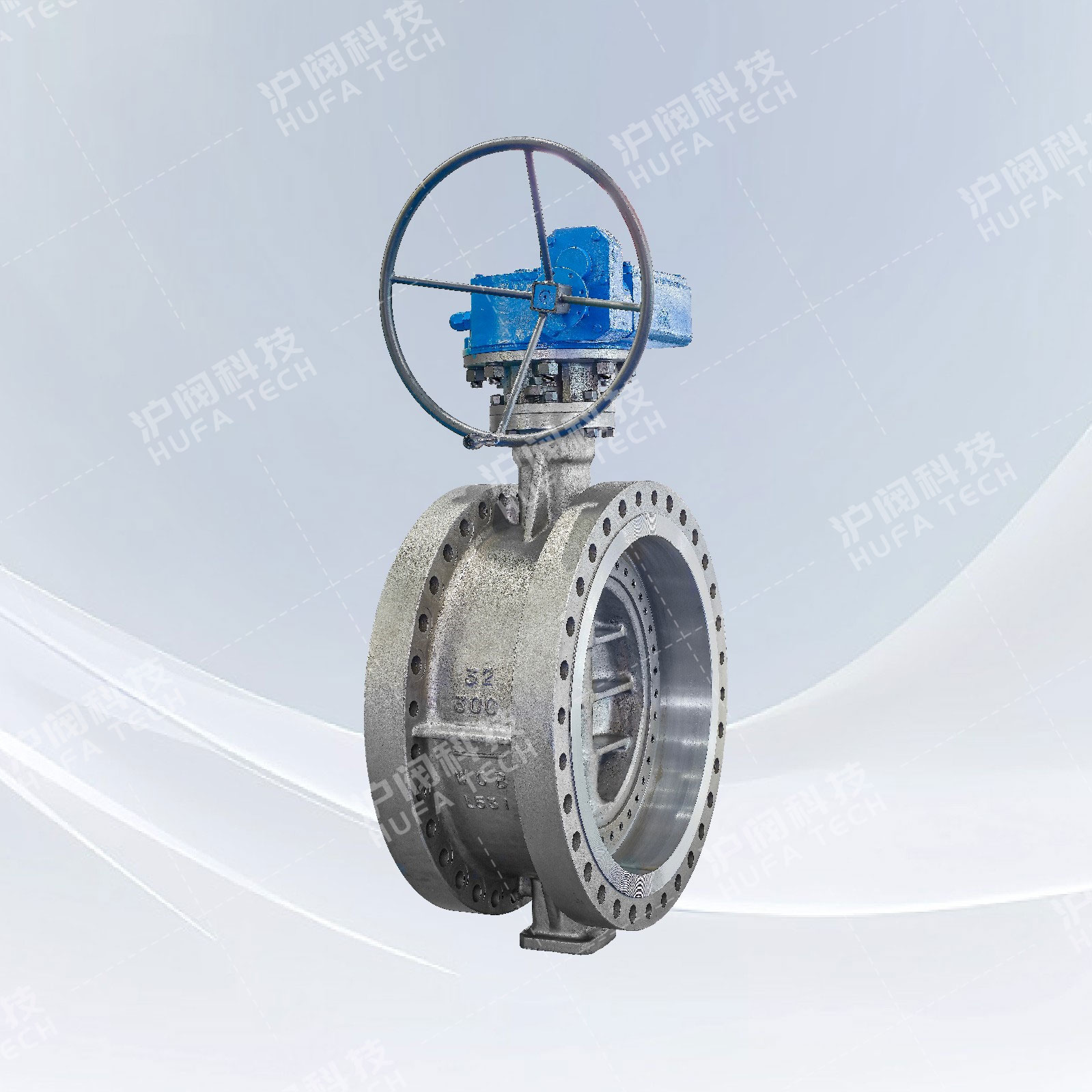
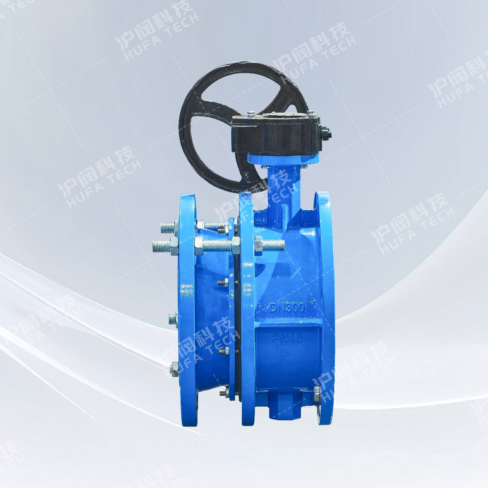
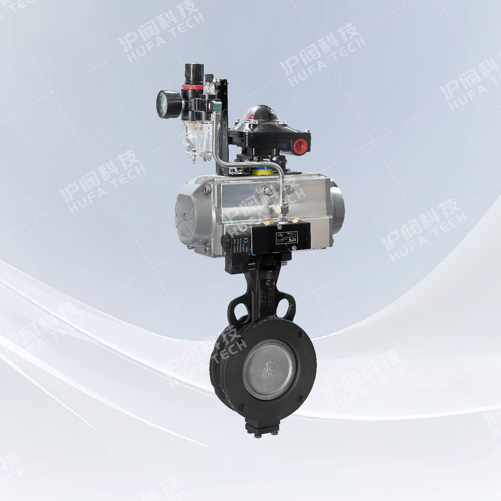
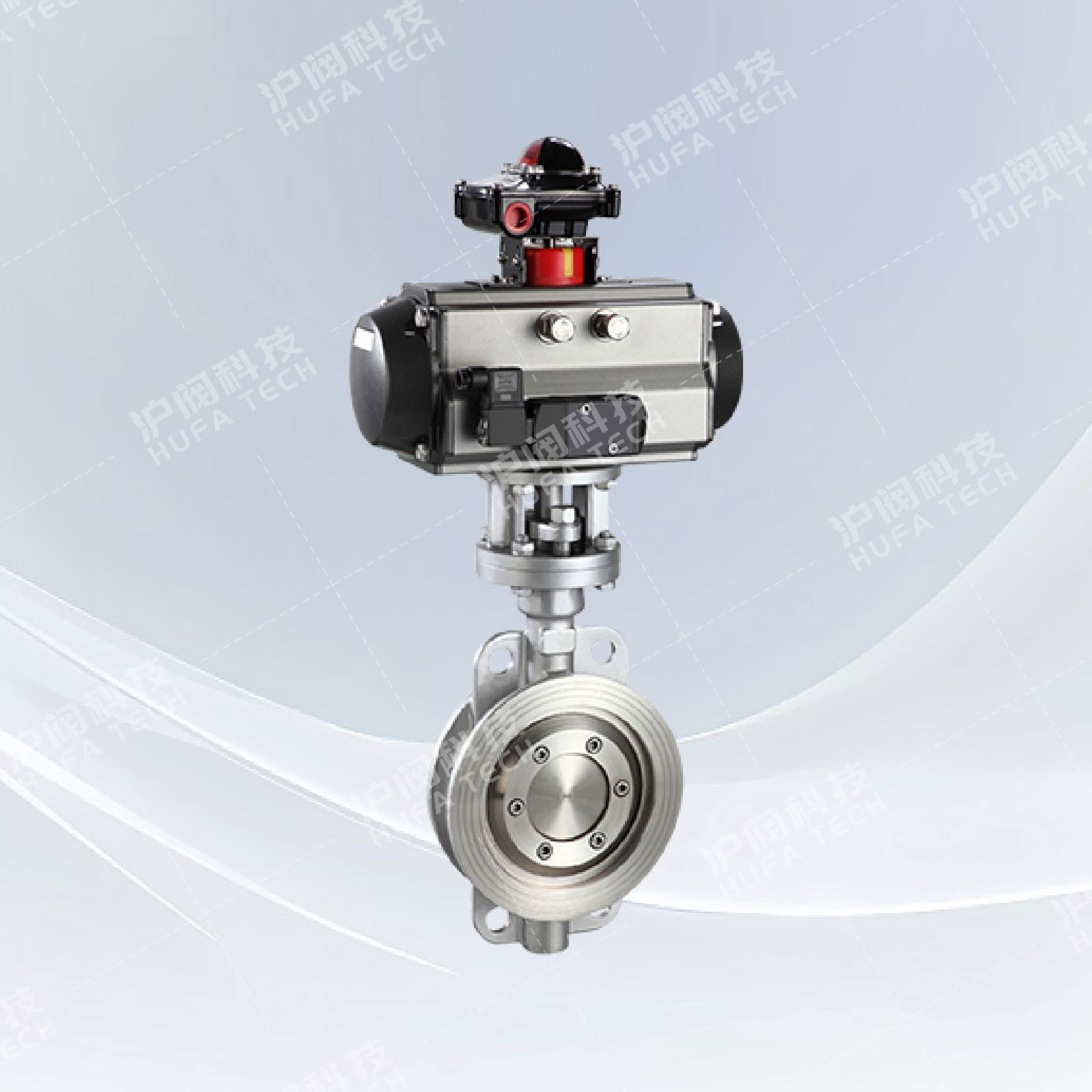
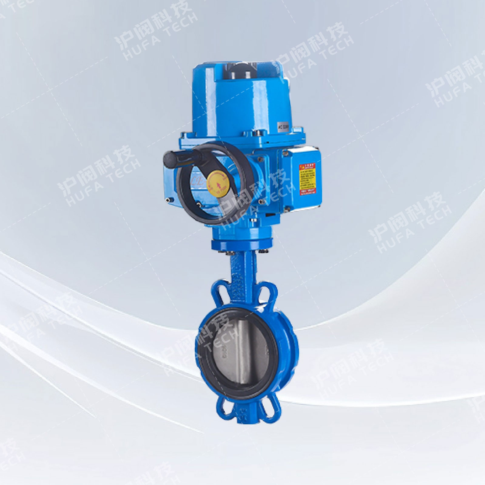
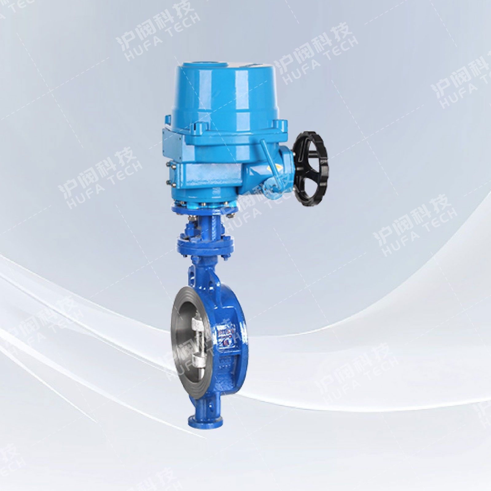
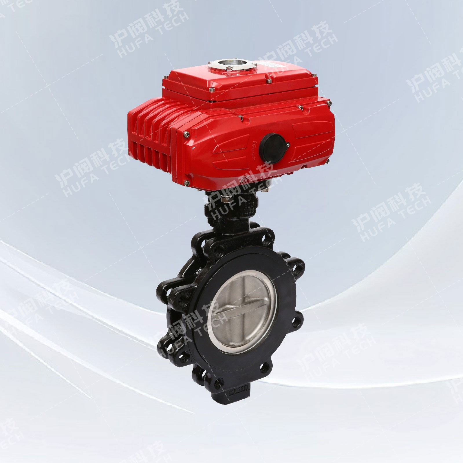
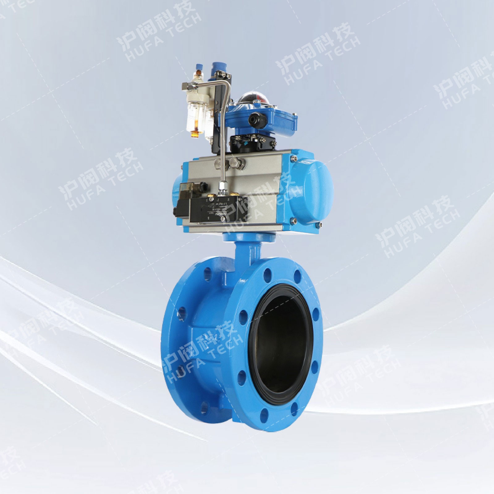
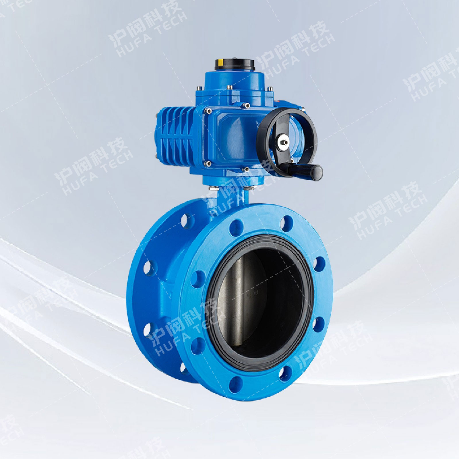
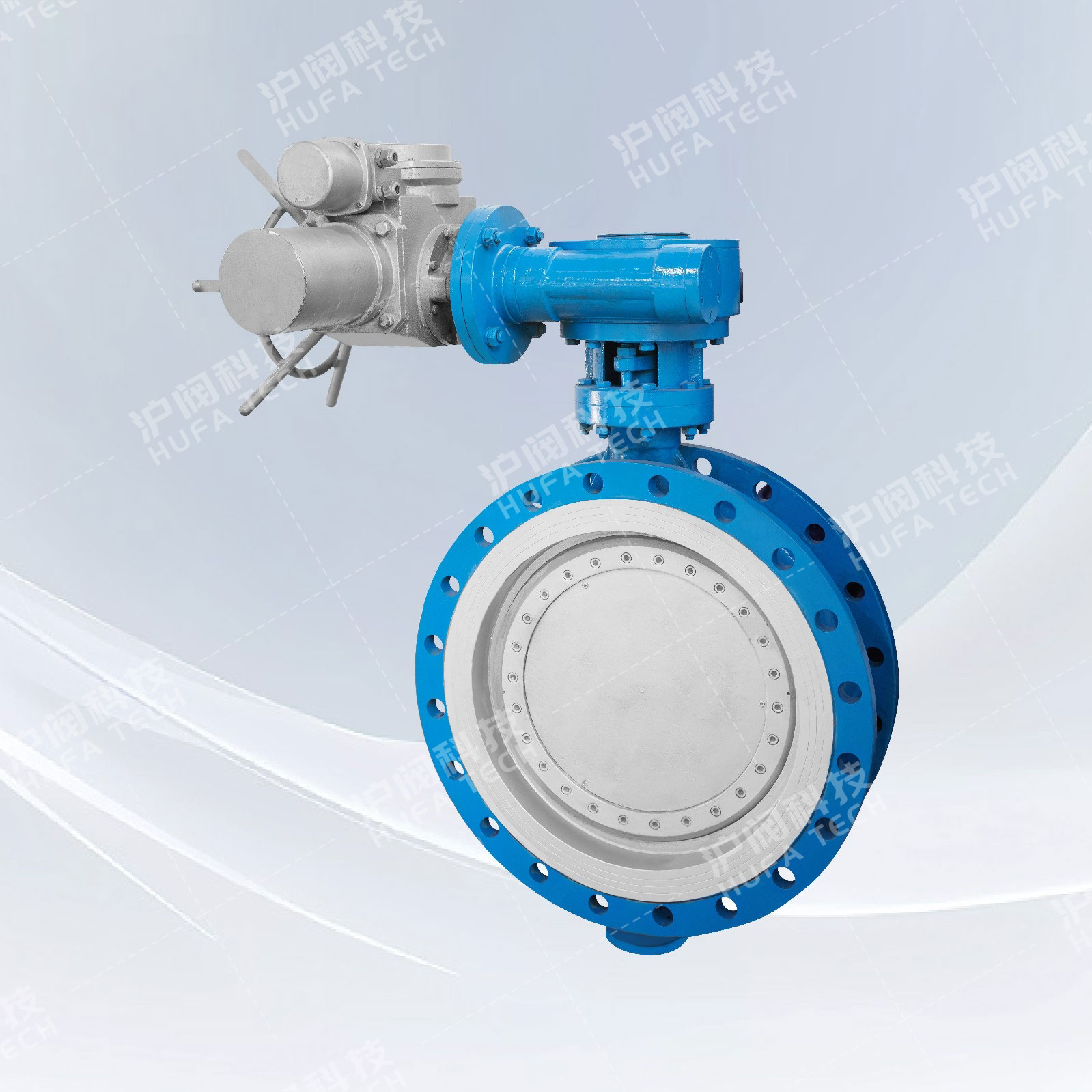
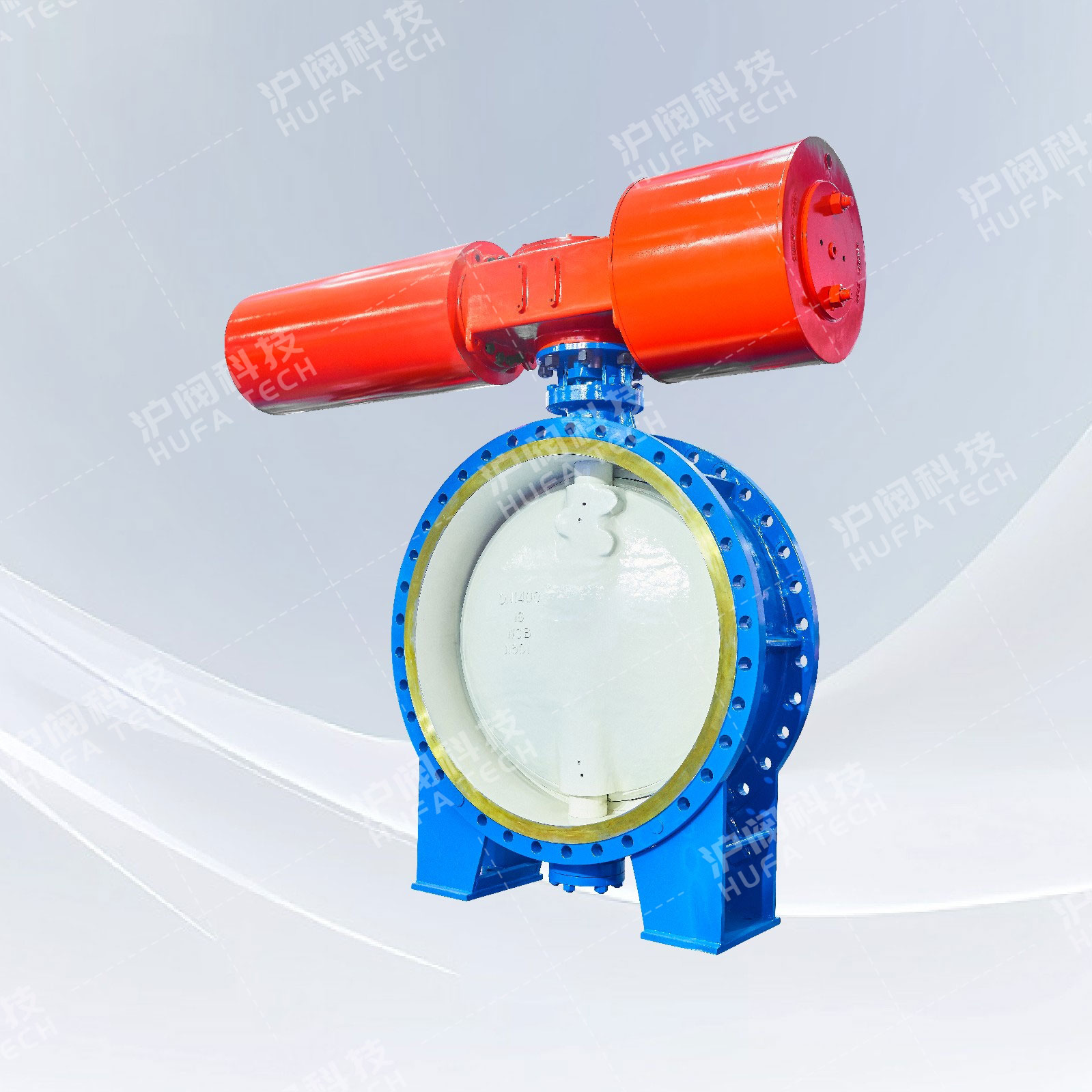
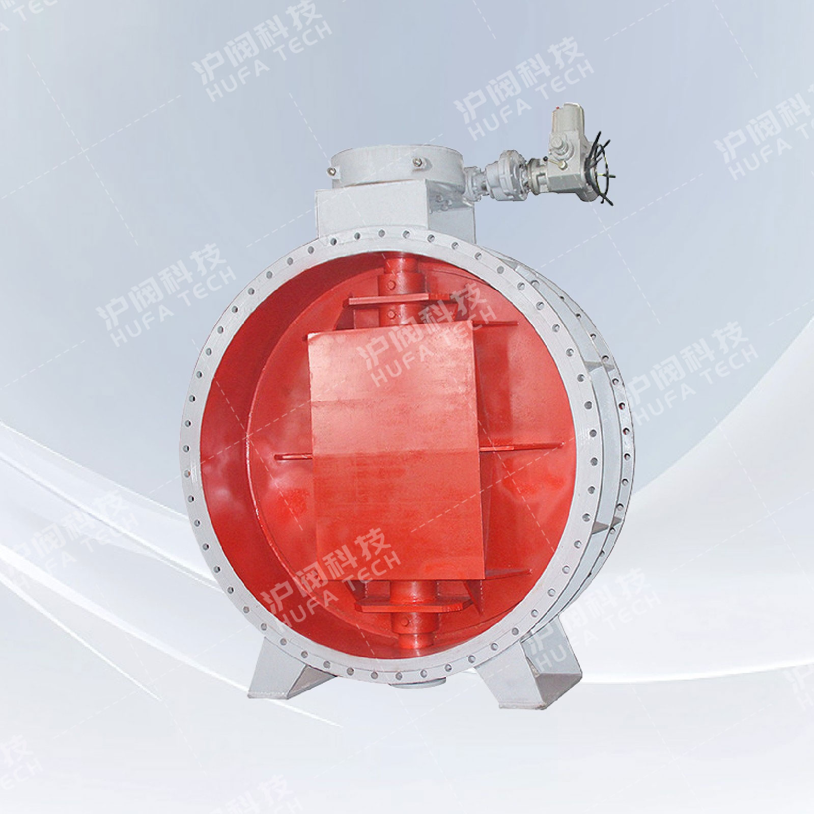
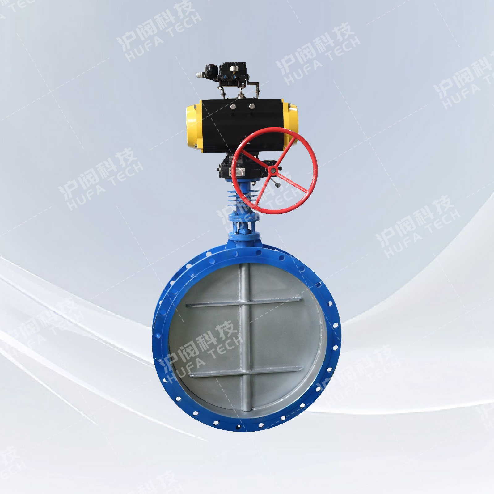
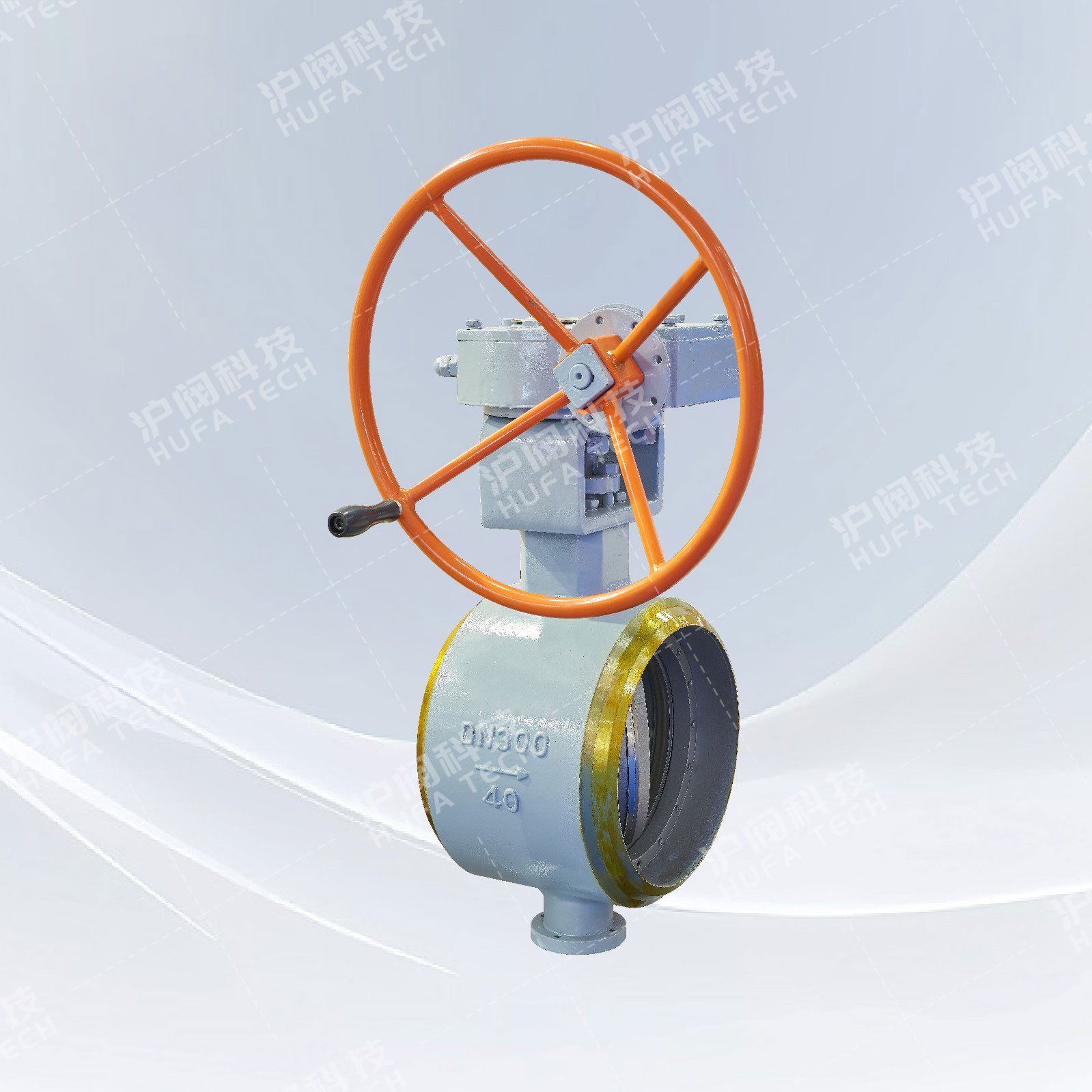
Flanged center plate butterfly valve (worm gear)
Technical Specifications
Product model: D341X
Nominal pressure: PN1.0 - 1.6 MPa
Nominal diameter: DN50 - DN1400
Connection type: Flange
Operating medium: Water, oil, gas and various corrosive media
Applicable temperature range: -10 to 150℃
Connection standards: GB·ANSI·DIN·API·ISO·BS
Valve body material: Cast iron; Machined cast iron
Valve seat material: Rubber
Valve plate material: Stainless steel Machined cast iron
Sales Hotline:
Product Details
Technical standards
1. As a device for regulating or cutting off the medium in pipelines.
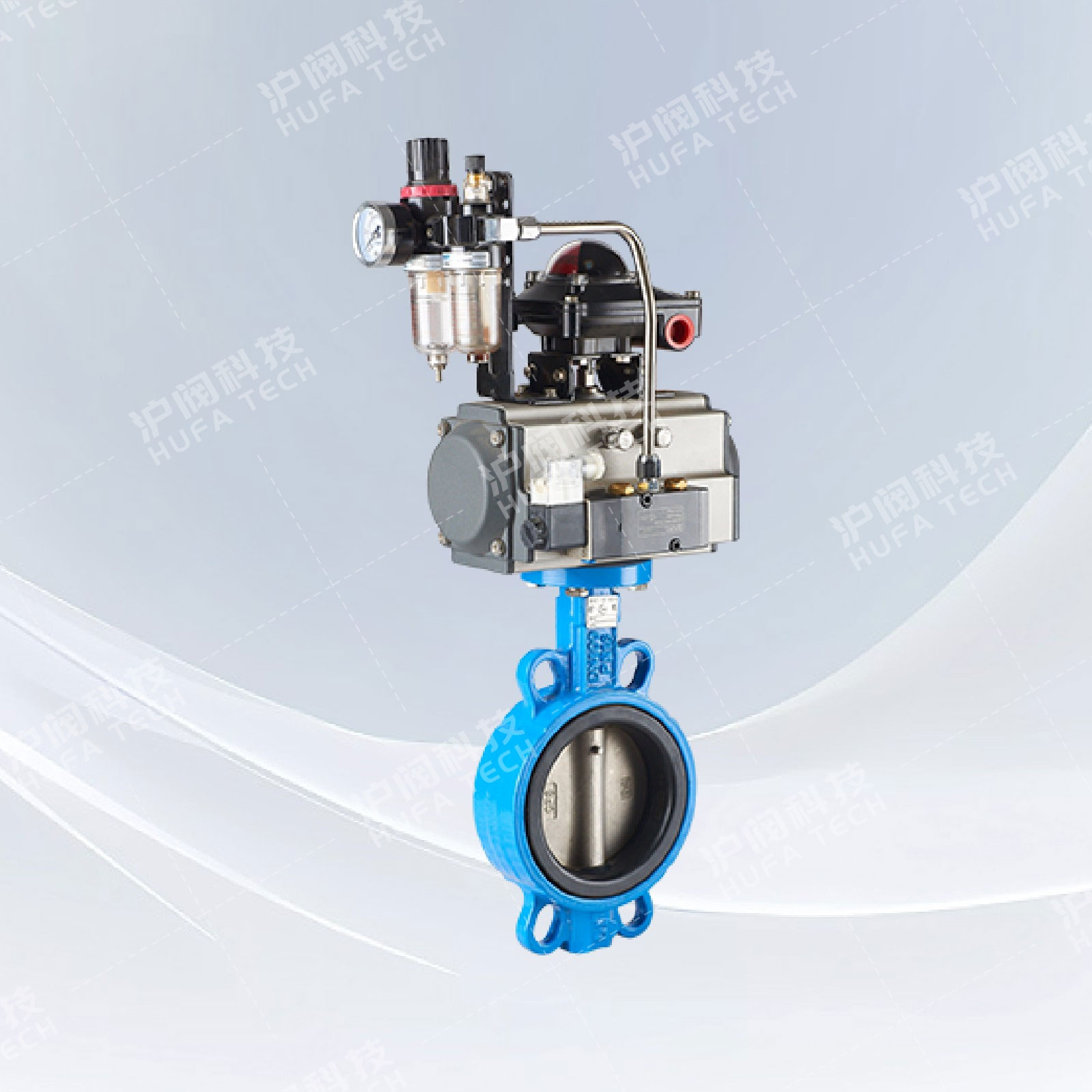
2. It is applicable to handle control devices (DN50~300), worm gear, electric and pneumatic control devices.
3. The design and manufacturing standards comply with GB/T12238.
4. The pressure test complies with GB/T13927.
5. The structural length complies with GB/T12221.
6. The side flange standard complies with GB/T17241.6.
Product features
1. It can be equipped with a handle, worm gear transmission, electric or pneumatic control devices.2. Reduce the torque of rotation, support the valve stem, and make it effectively separated from the valve body to reduce the wear of the valve stem.
3. After polishing treatment, it has a precise fit with the valve seat.
4. Achieve zero leakage requirement for the air tightness test. The opening and closing torque is small, prolonging the service life of the valve seat.
5. The valve stem seal is not prone to deformation, thus avoiding the common valve stem leakage phenomenon.
6. High precision, strong strength, suitable for installation of handles and other control devices.
7. Firmly connects the valve stem and valve plate, with features of anti-vibration and anti-detachment, and easy to replace.
8. High precision, strong reliability, convenient for controlling the opening and closing of the valve plate.
9. Good overall support, stable fixation, resistant to tension and leakage.
10. Assist in preventing end shaft leakage.
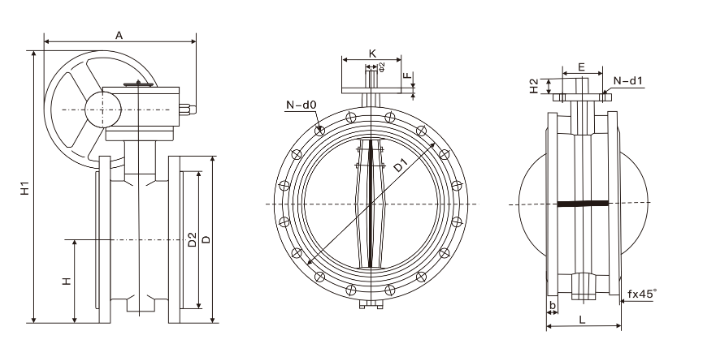
Main dimensions and weight(PN1.0/1.6MPa)
| DN | L | D | D1 | D2 | b | f | N-d0 | A | K | E | F | H | H1 | H2 | Φ2 | N-d1 |
| 50 | 108 | 165 | 125 | 102 | 18 | 3 | 4-Φ18 | 180 | 65 | 50 | 13 | 83 | 338 | 28 | 12.6 | 4-Φ7 |
| 65 | 112 | 185 | 145 | 122 | 18 | 3 | 8-Φ18 | 180 | 65 | 50 | 13 | 93 | 358 | 28 | 12.6 | 4-Φ7 |
| 80 | 114 | 200 | 160 | 138 | 20 | 3 | 8-Φ18 | 245 | 65 | 50 | 13 | 100 | 413 | 28 | 12.6 | 4-Φ7 |
| 100 | 127 | 220 | 180 | 158 | 20 | 3 | 8-Φ18 | 240 | 90 | 70 | 13 | 114 | 428 | 28 | 15.77 | 4-Φ10 |
| 125 | 140 | 250 | 210 | 188 | 22 | 3 | 8-Φ18 | 240 | 90 | 70 | 13 | 125 | 444 | 28 | 18.92 | 4-Φ10 |
| 150 | 140 | 285 | 240 | 212 | 22 | 3 | 8-Φ22 | 350 | 90 | 70 | 13 | 143 | 553 | 28 | 18.92 | 4-Φ10 |
| 200 | 152 | 340 | 295 | 268 | 24 | 3 | 12-Φ22 | 350 | 125 | 102 | 13 | 170 | 678 | 38 | 22.1 | 4-Φ12 |
| 250 | 165 | 405 | 355 | 320 | 26 | 3 | 12-Φ26 | 550 | 125 | 102 | 13 | 198 | 742 | 38 | 28.45 | 4-Φ12 |
| 300 | 178 | 460 | 410 | 378 | 28 | 4 | 12-Φ26 | 600 | 125 | 102 | 20 | 223 | 803 | 38 | 31.6 | 4-Φ12 |
| 350 | 190 | 520 | 470 | 438 | 30 | 4 | 16-Φ26 | 600 | 150 | 125 | 20 | 270 | 866 | 45 | 31.6 | 4-Φ14 |
| 400 | 216 | 580 | 525 | 490 | 32 | 4 | 16-Φ30 | 600 | 175 | 140 | 20 | 300 | 940 | 51 | 33.15 | 4-Φ18 |
| 450 | 222 | 640 | 585 | 550 | 40 | 4 | 20-Φ30 | 750 | 175 | 140 | 20 | 340 | 995 | 51 | 37.95 | 4-Φ18 |
| 500 | 229 | 715 | 650 | 610 | 44 | 4 | 20-Φ33 | 750 | 175 | 140 | 22 | 355 | 1058 | 57 | 41.12 | 4-Φ18 |
| 600 | 267 | 840 | 770 | 725 | 54 | 5 | 20-Φ36 | 750 | 210 | 165 | 30 | 410 | 1163 | 70 | 50.63 | 4-Φ22 |
| 700 | 292 | 910 | 840 | 795 | 40 | 5 | 24-Φ36 | 750 | 300 | 254 | 30 | 478 | 1283 | 66 | 63.35 | 8-Φ18 |
| 800 | 318 | 1025 | 950 | 900 | 42 | 5 | 24-Φ39 | 750 | 300 | 254 | 30 | 529 | 1398 | 66 | 63.35 | 8-Φ18 |
| 900 | 330 | 1125 | 1050 | 1000 | 44 | 5 | 28-Φ39 | 1250 | 300 | 254 | 34 | 584 | 1498 | 118 | 75 | 8-Φ18 |
| 1000 | 410 | 1255 | 1170 | 1115 | 46 | 5 | 28-Φ42 | 1500 | 300 | 254 | 34 | 357 | 1608 | 142 | 85 | 8-Φ18 |
| 1200 | 470 | 1485 | 1390 | 1330 | 52 | 5 | 32-Φ48 | 1500 | 350 | 298 | 34 | 799 | 1876 | 150 | 105 | 8-Φ22 |

 Check the mobile website