
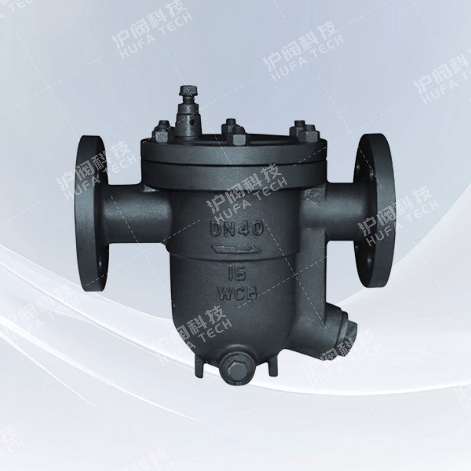
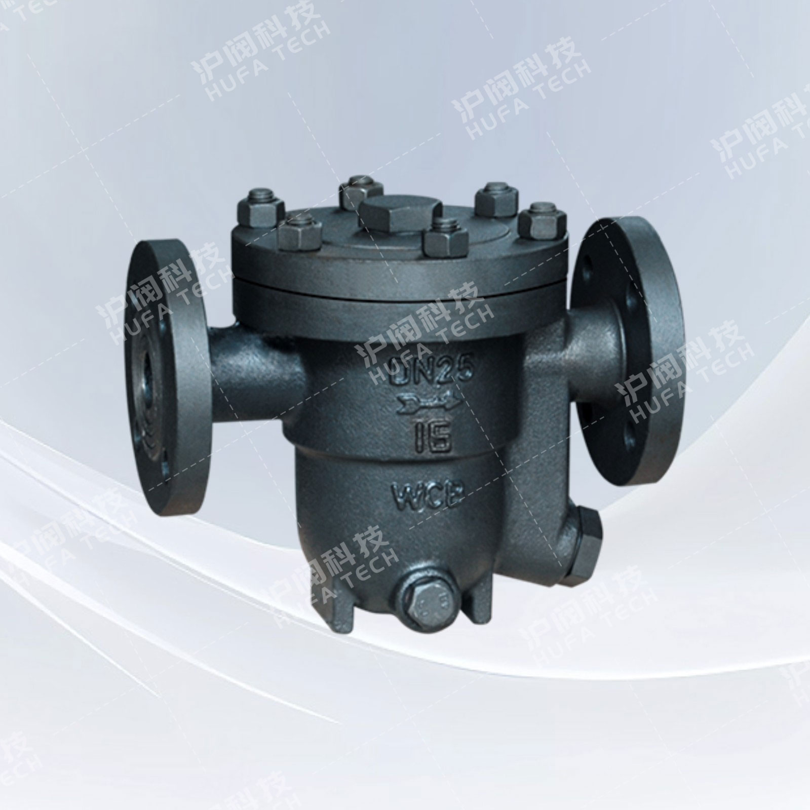
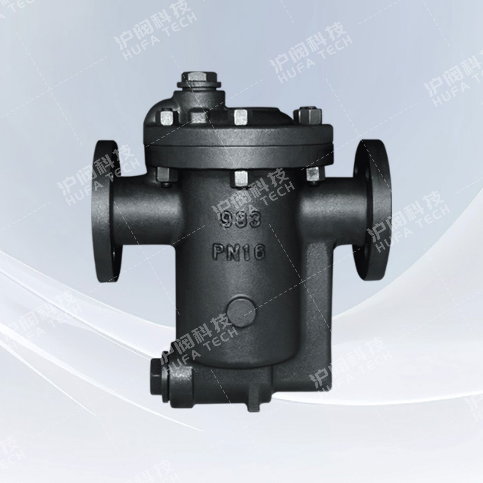
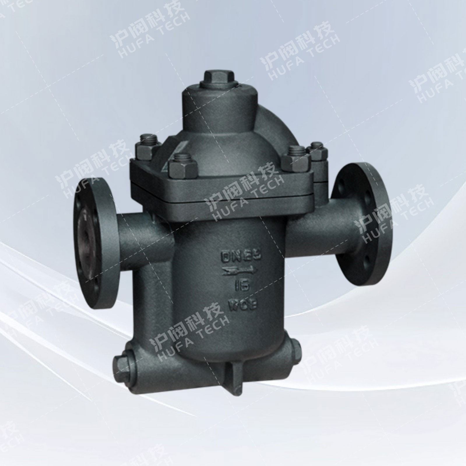
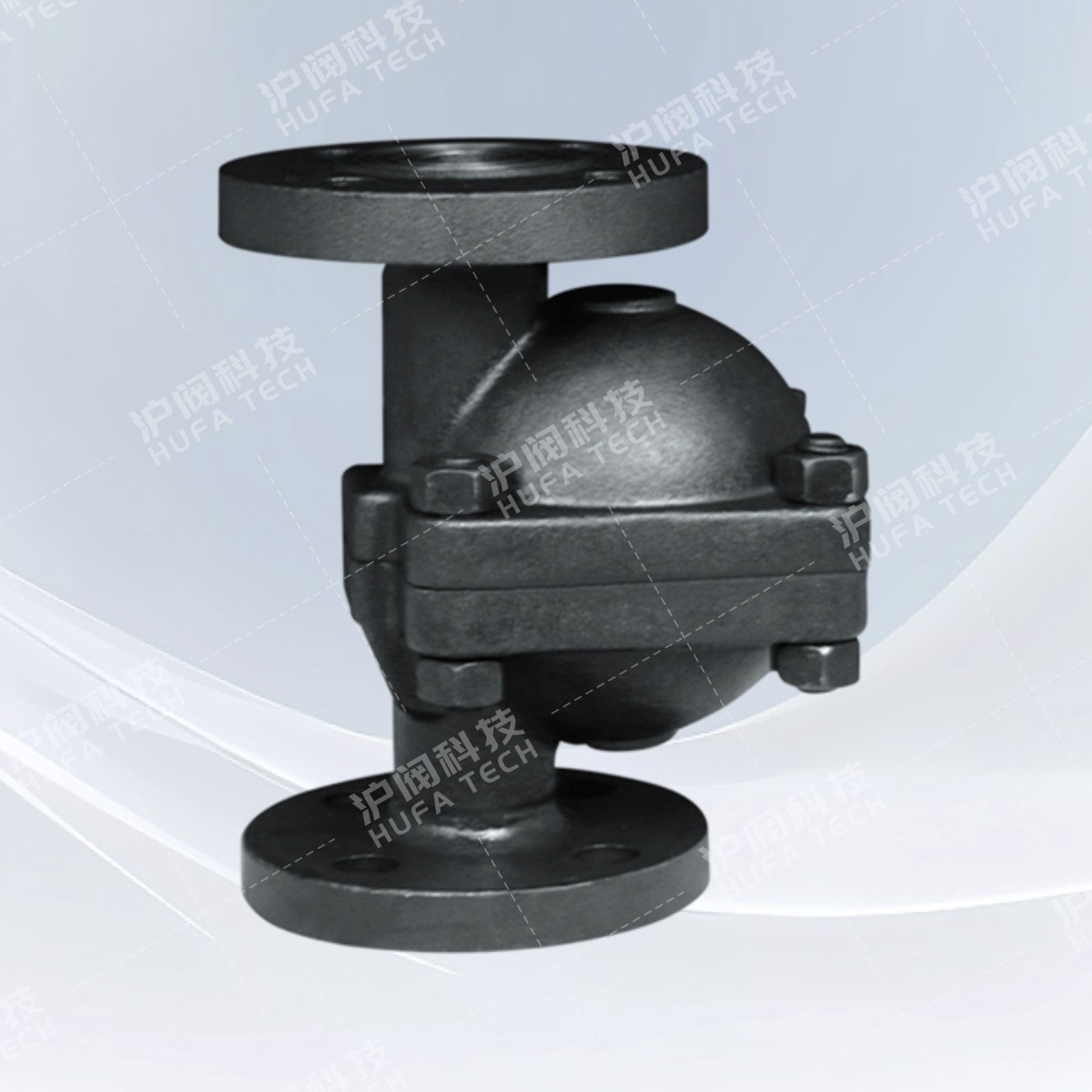
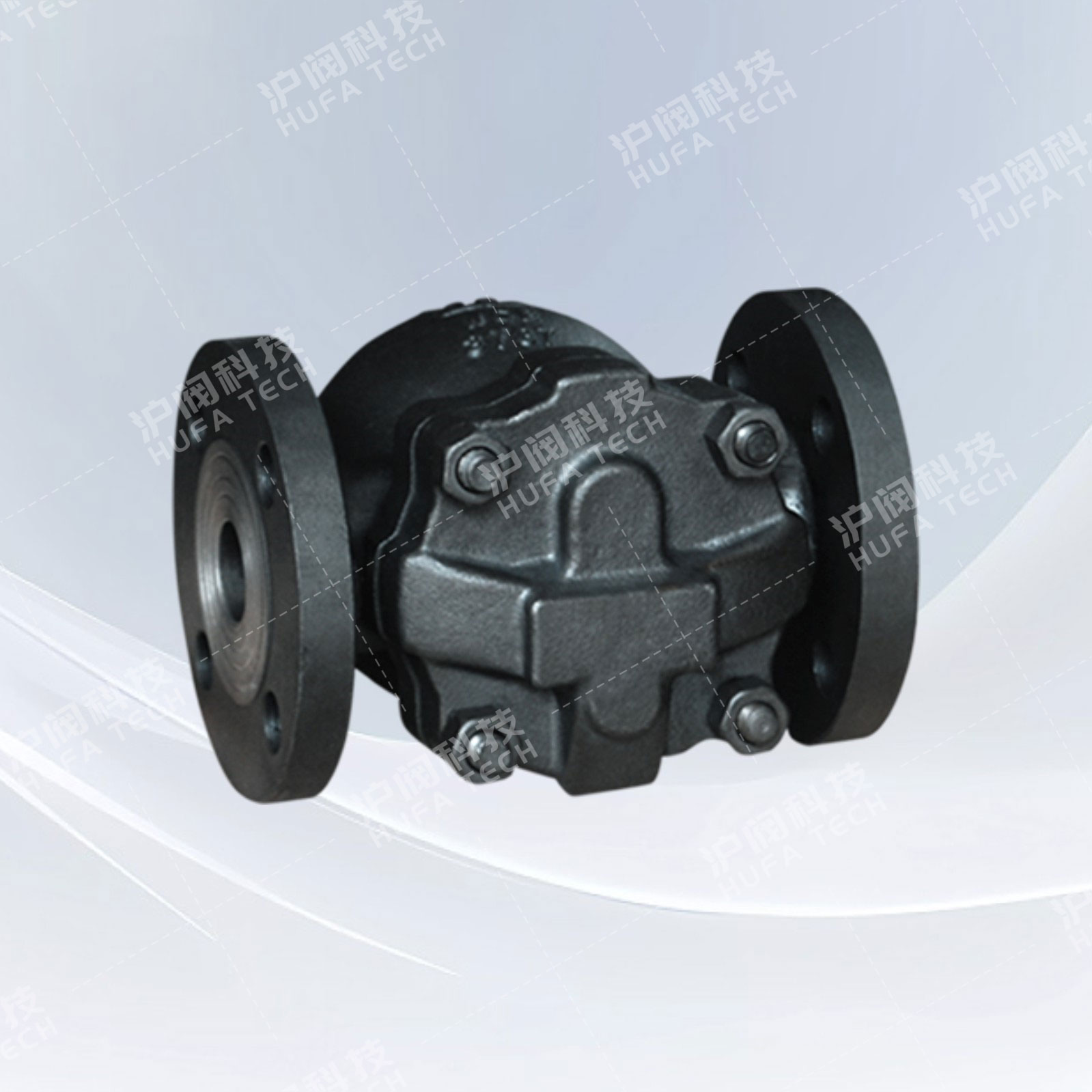
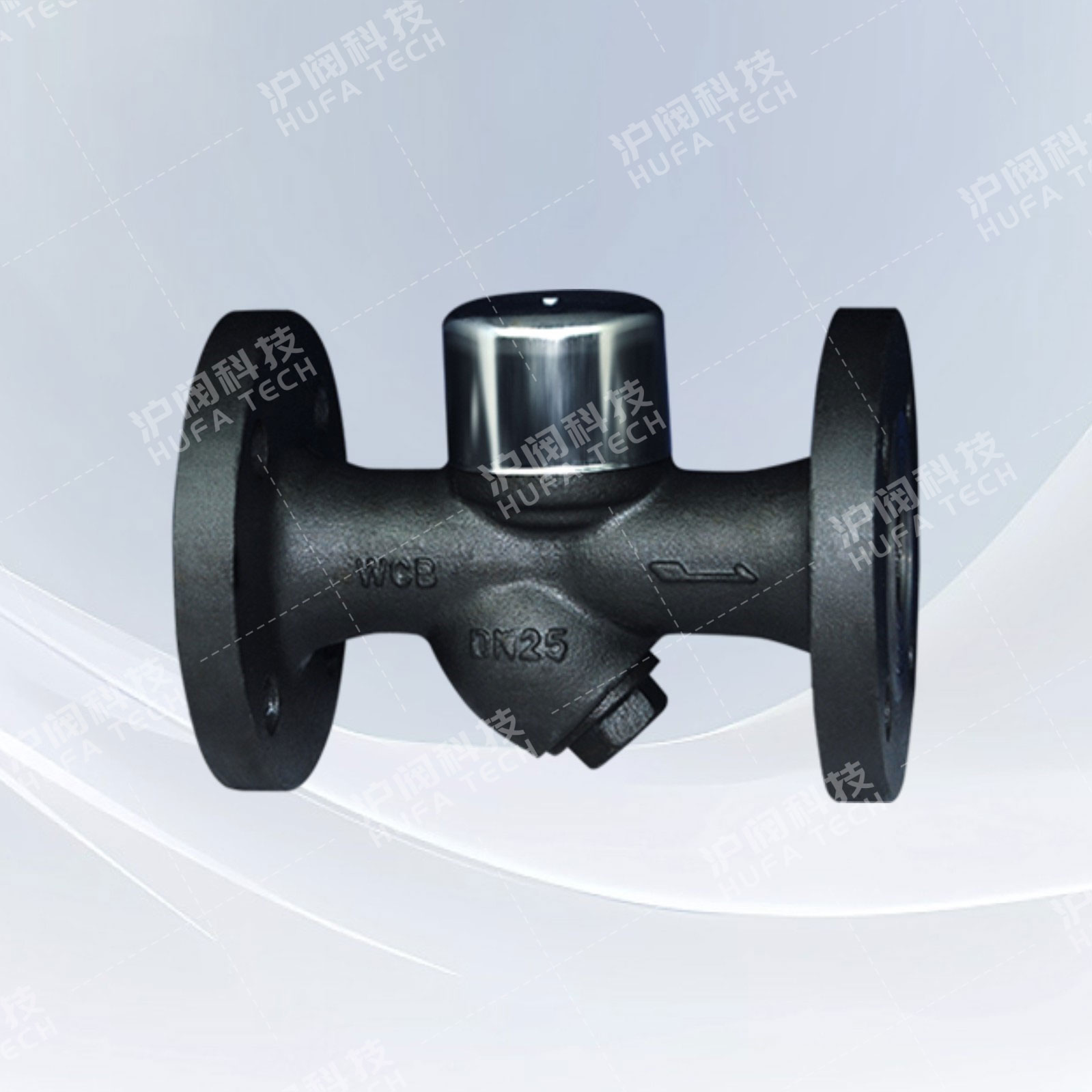
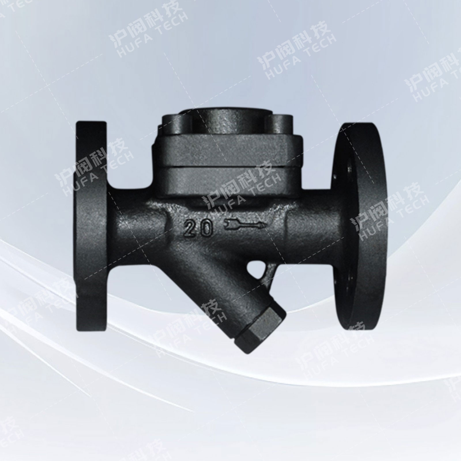
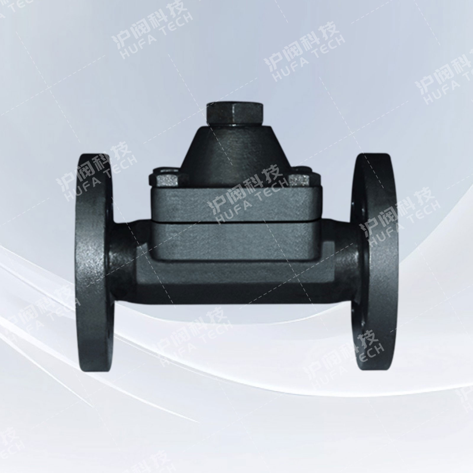
Free-Floating Ball Type Steam Trap (Model CS41H)
Technical Specifications
Product model: CS41H
Nominal diameter: DN15 - 150mm
Nominal pressure: PN1.6 - 4.0MPa
Working temperature: ≤ 350℃
Main materials: Forged steel, stainless steel, titanium alloy steel, chromium-molybdenum steel, low-temperature steel
Drive method: Manual
Design specification: GB/T 9093
Structural length: GB/T 12250
Thread connection: ISO 228
Flange connection: JB/T 79, GB 9113, ANSI B16.34
Testing and inspection: GB/T 13927
Sales Hotline:
Product Details
Product Overview
The free-floating ball type steam trap (CS41H model) is an automatic valve. It is particularly suitable for applications with low pressure, low drainage volume, and high requirements for temperature stability. It is especially applicable to steam equipment that does not retain condensate. The main working principle of the free-floating ball type steam trap is based on the principle of buoyancy, causing the floating ball inside the valve to move up and down with the water level change, thereby achieving the valve's opening and closing function, that is, the function of draining and blocking steam. It is widely used in various steam pipelines.
Structural features
1. It can continuously drain water, has stable performance, large drainage capacity, and low leakage volume.
2. It can drain continuous saturated water, resulting in less condensate water accumulation in the equipment, faster temperature rise, and stable heating temperature.
3. It has an automatic cold air discharge device, without vapor lock phenomenon, and operates smoothly without noise.
Main dimensions of the shape
| Product model | Bore diameter | Size | |||||||
| DN | L | H | D | D1 | D2 | b | f | Z-Φd | |
| CS41H-16/25/40C-B | 15 | 195 | 195 | 95 | 65 | 45 | 14 | 2 | 4-Φ14 |
| 20 | 195 | 200 | 105 | 75 | 55 | 14 | 2 | 4-Φ14 | |
| 25 | 215 | 225 | 115 | 85 | 65 | 14 | 2 | 4-Φ14 | |
| CS41H-16/25/40C-D | 25 | 270 | 245 | 115 | 85 | 65 | 14 | 2 | 4-Φ14 |
| 32 | 270 | 250 | 135 | 100 | 78 | 16 | 2 | 4-Φ18 | |
| 40 | 280 | 290 | 145 | 110 | 85 | 16 | 3 | 4-Φ18 | |
| 50 | 290 | 300 | 160 | 125 | 100 | 16 | 3 | 4-Φ18 | |
| CS41H-16/25C-F | 50 | 410 | 380 | 160 | 125 | 100 | 16 | 3 | 4-Φ18 |
| 65 | 410 | 380 | 180 | 145 | 120 | 18 | 3 | 4-Φ18 | |
| 80 | 430 | 420 | 195 | 160 | 135 | 20 | 3 | 8-Φ18 | |
| 100 | 430 | 440 | 215 | 180 | 155 | 20 | 3 | 8-Φ18 | |
| 125 | 480 | 510 | 245 | 210 | 185 | 22 | 3 | 8-Φ18 | |
| 150 | 480 | 510 | 280 | 240 | 210 | 24 | 3 | 8-Φ23 | |
 Check the mobile website