
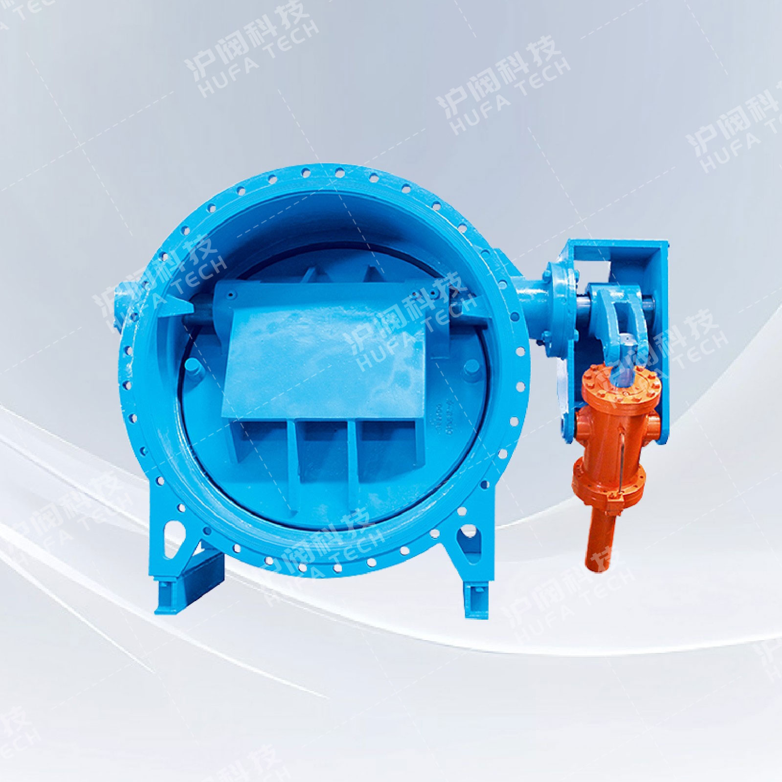
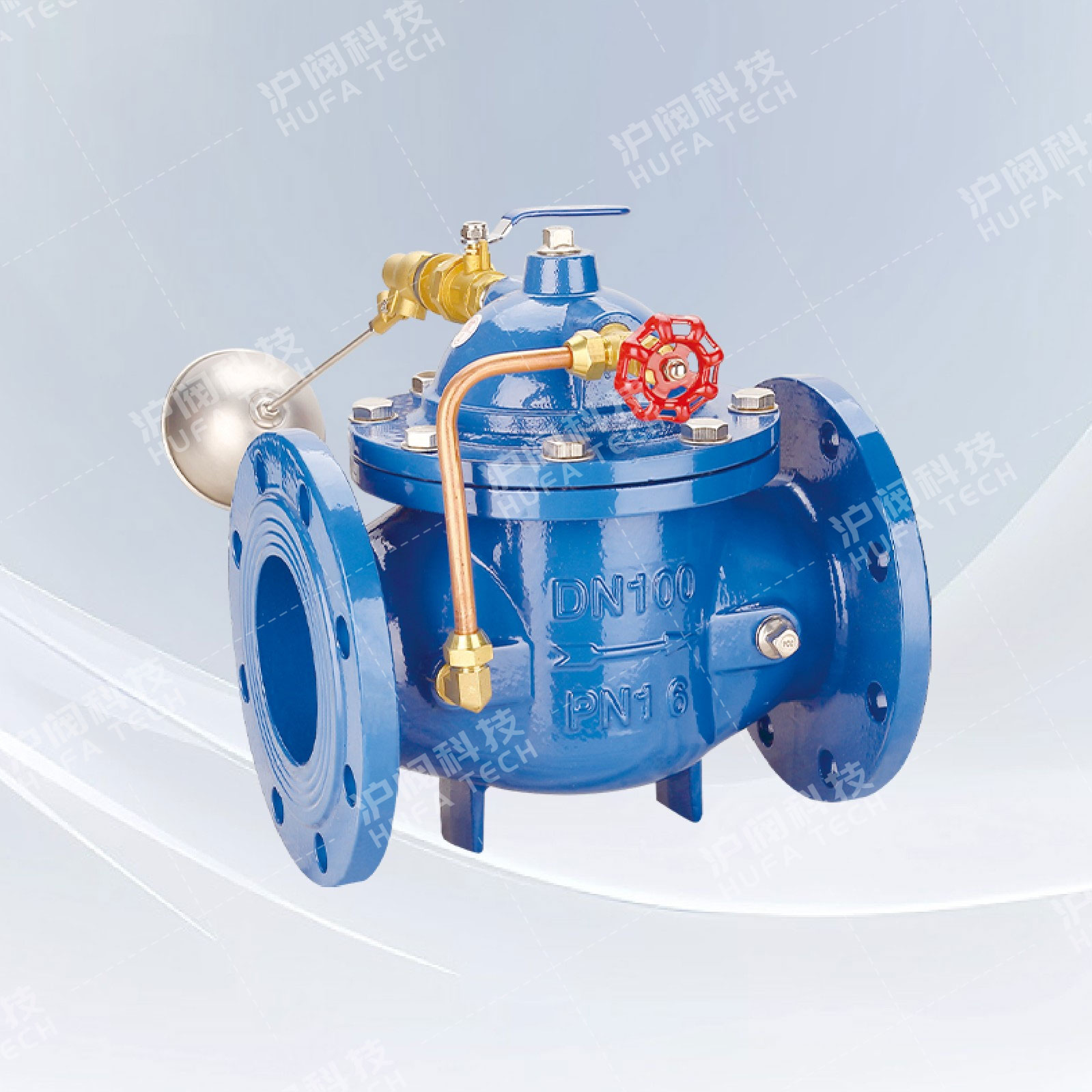
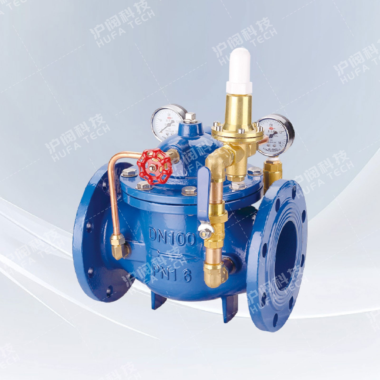
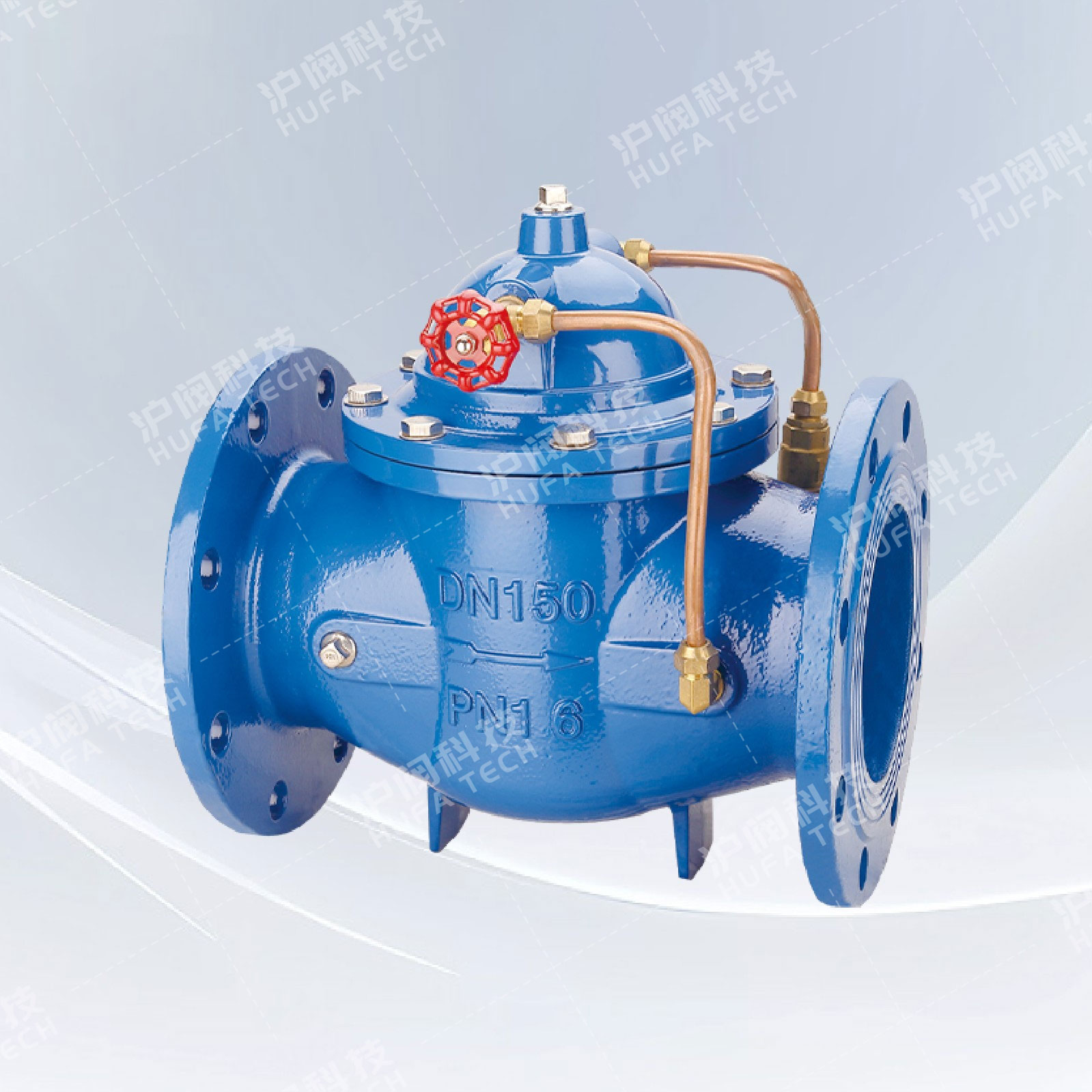
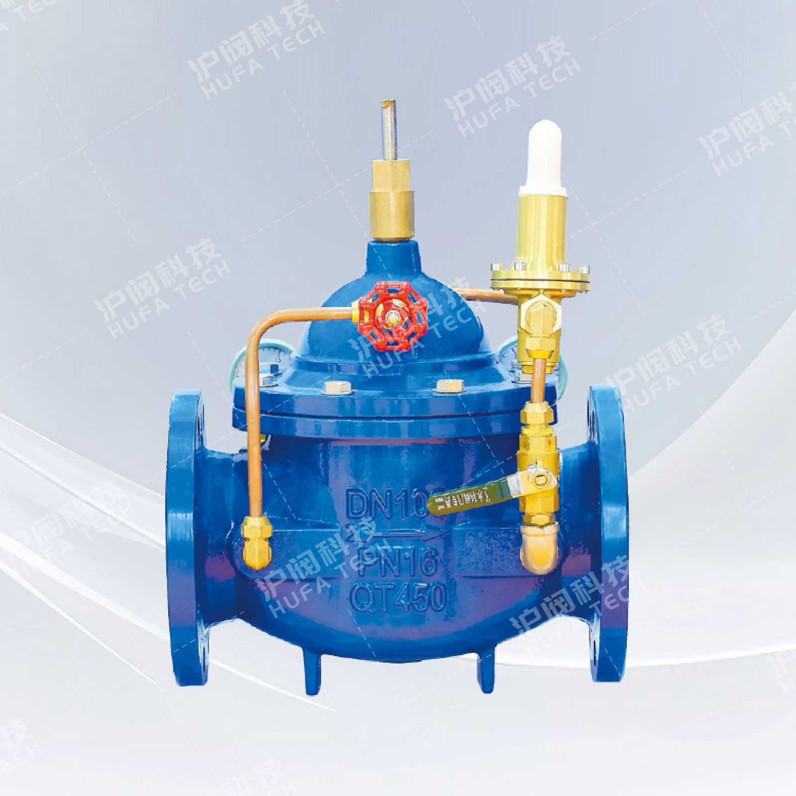
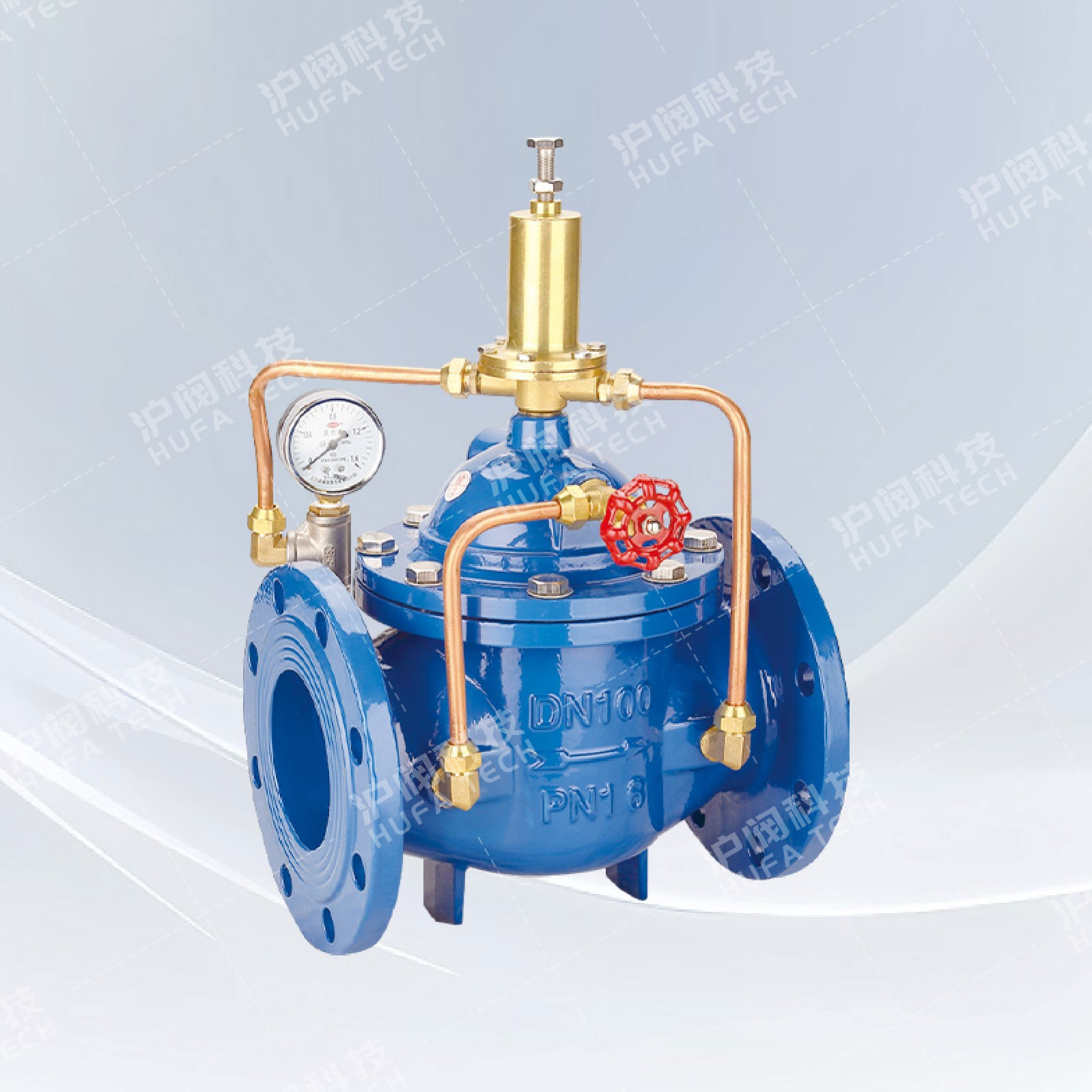
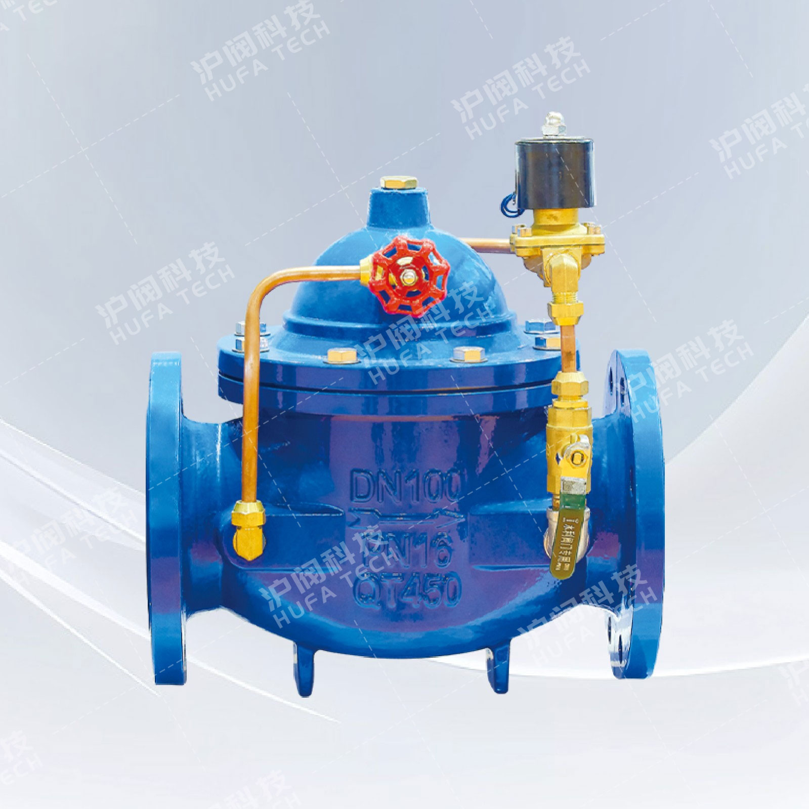
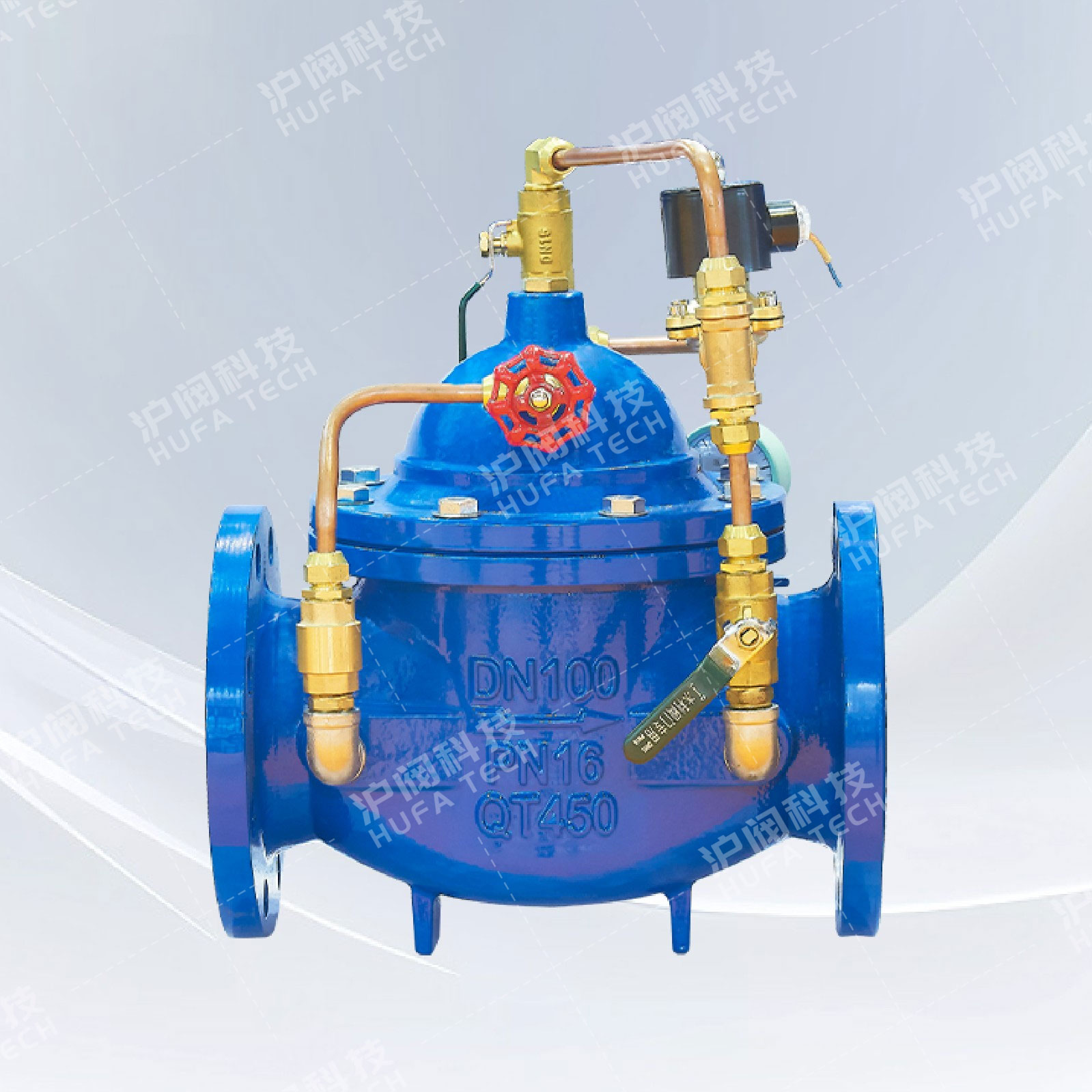
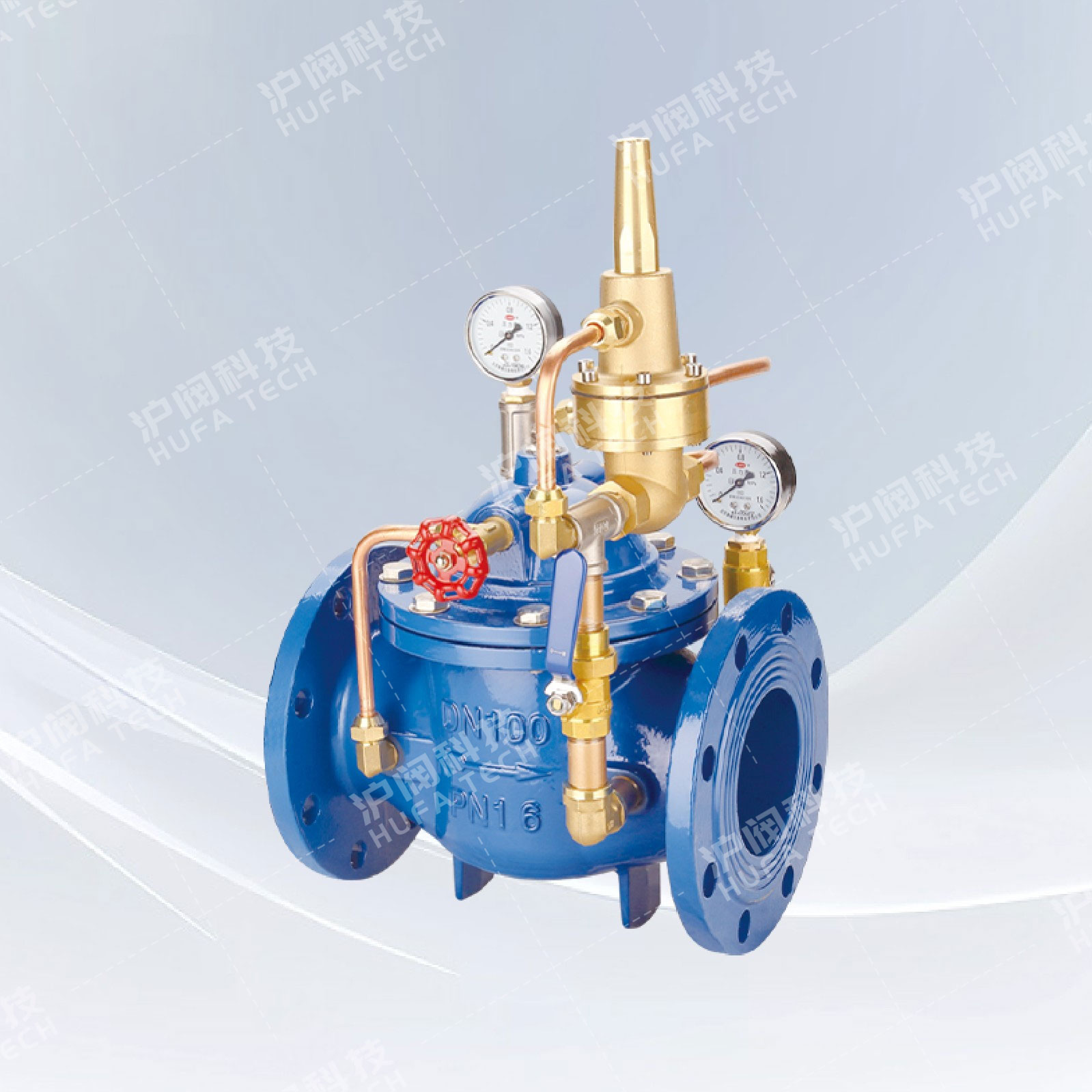
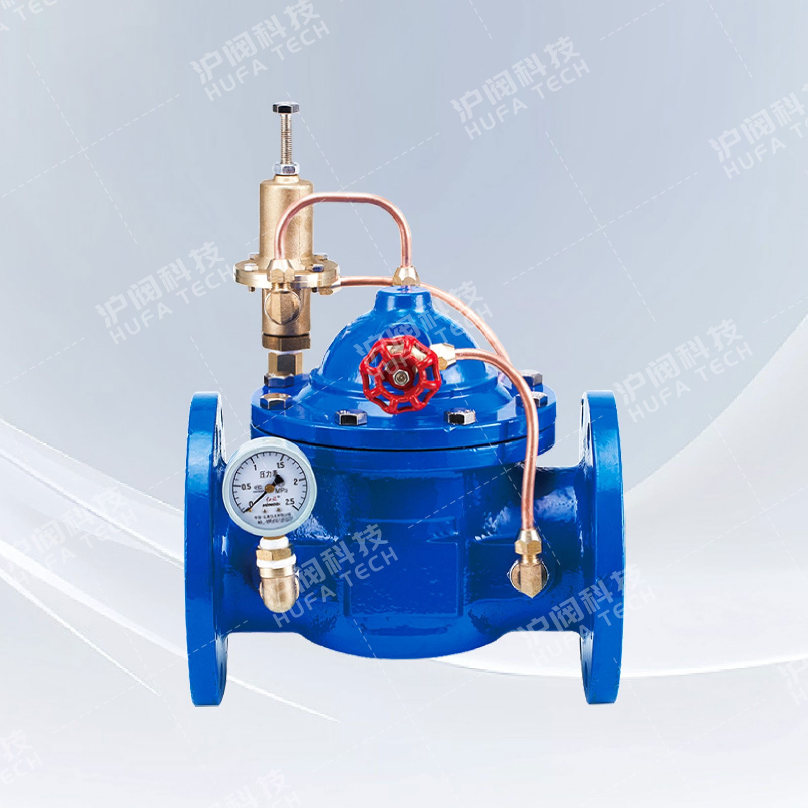
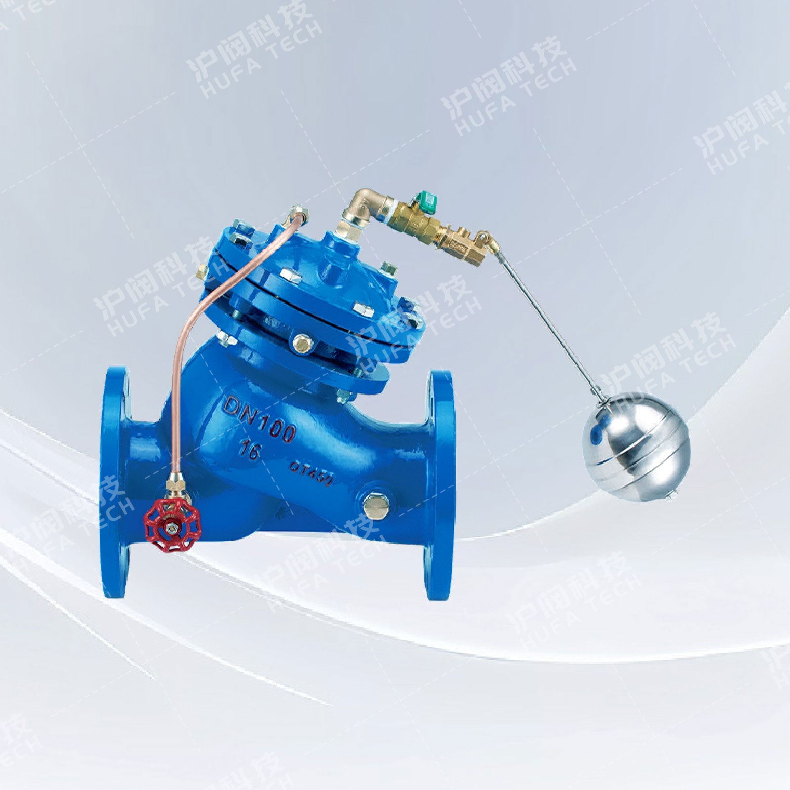
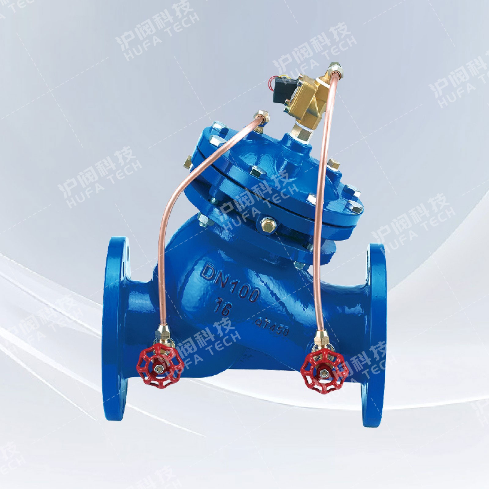
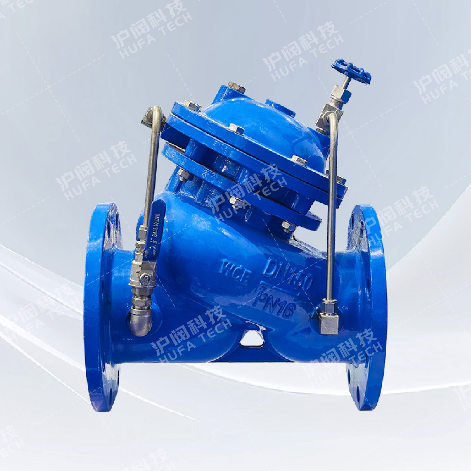
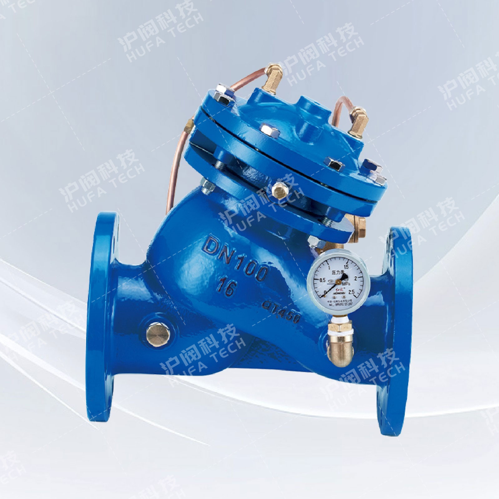
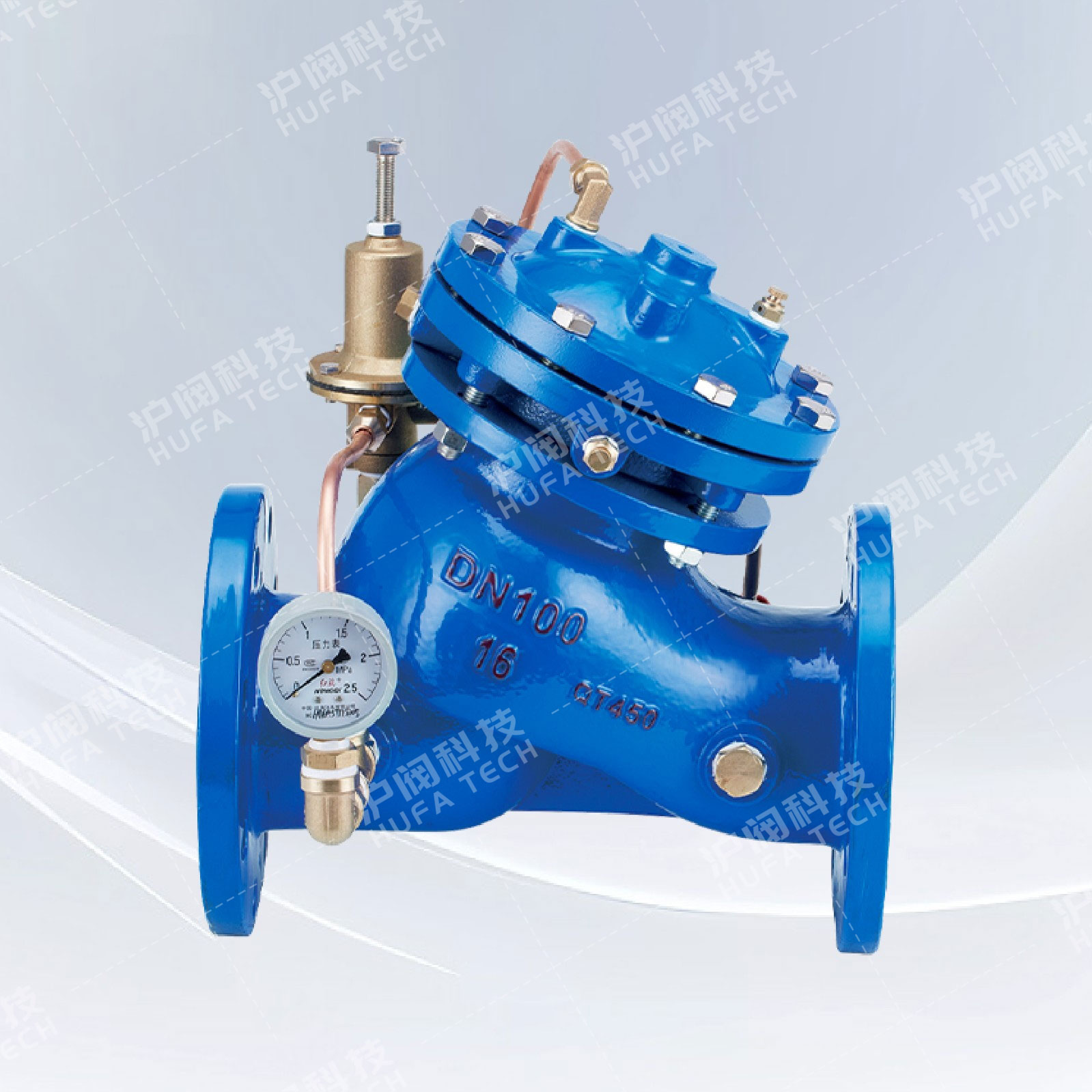
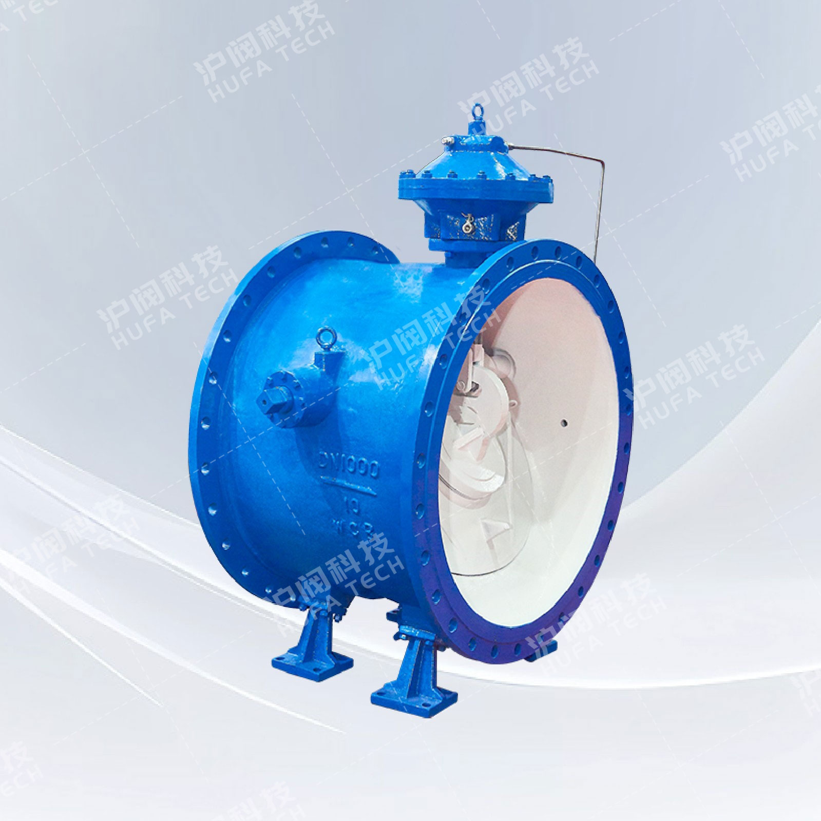
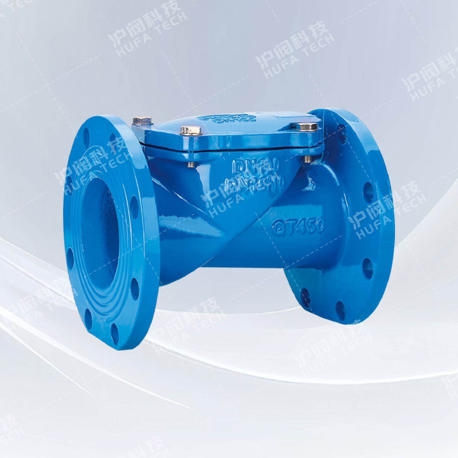
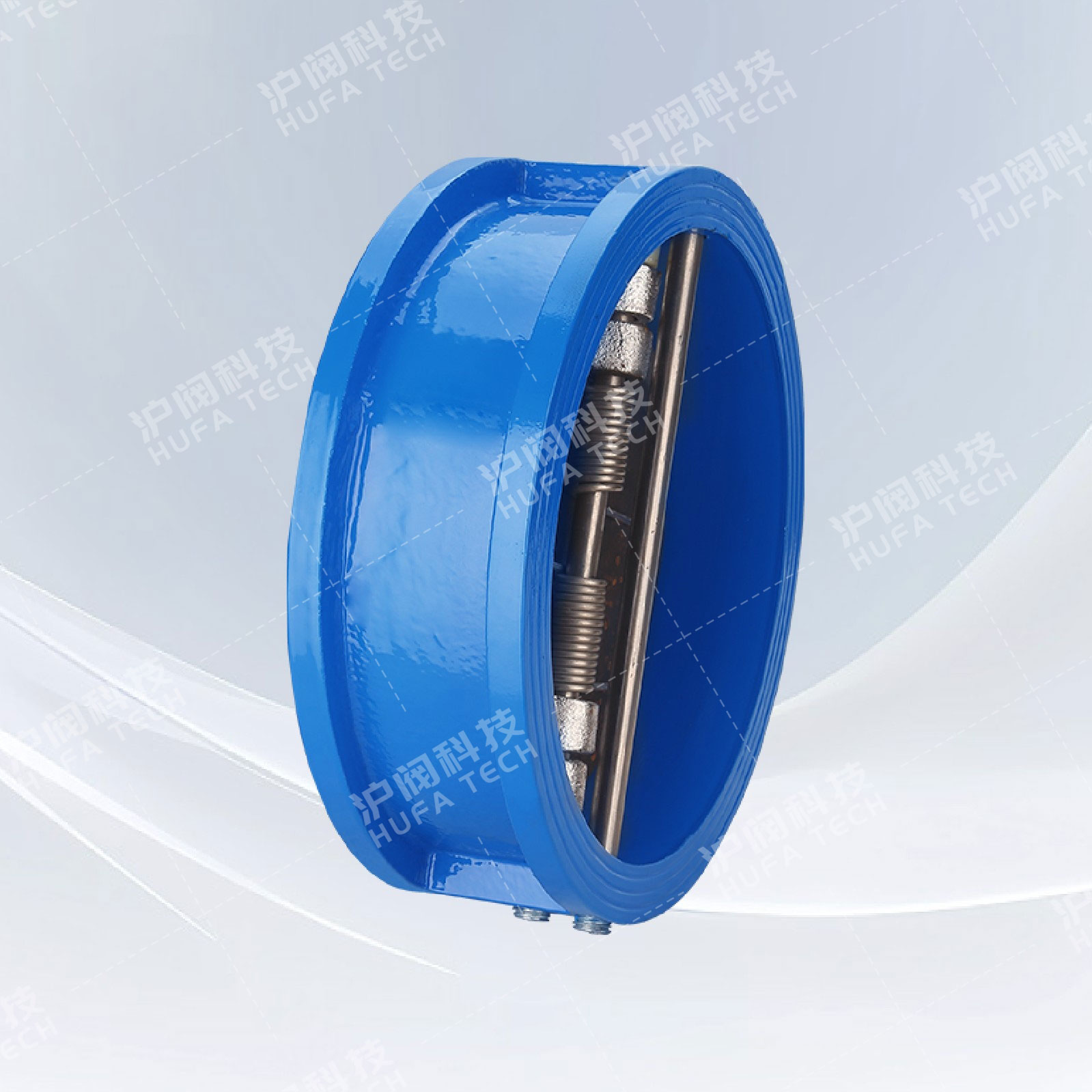
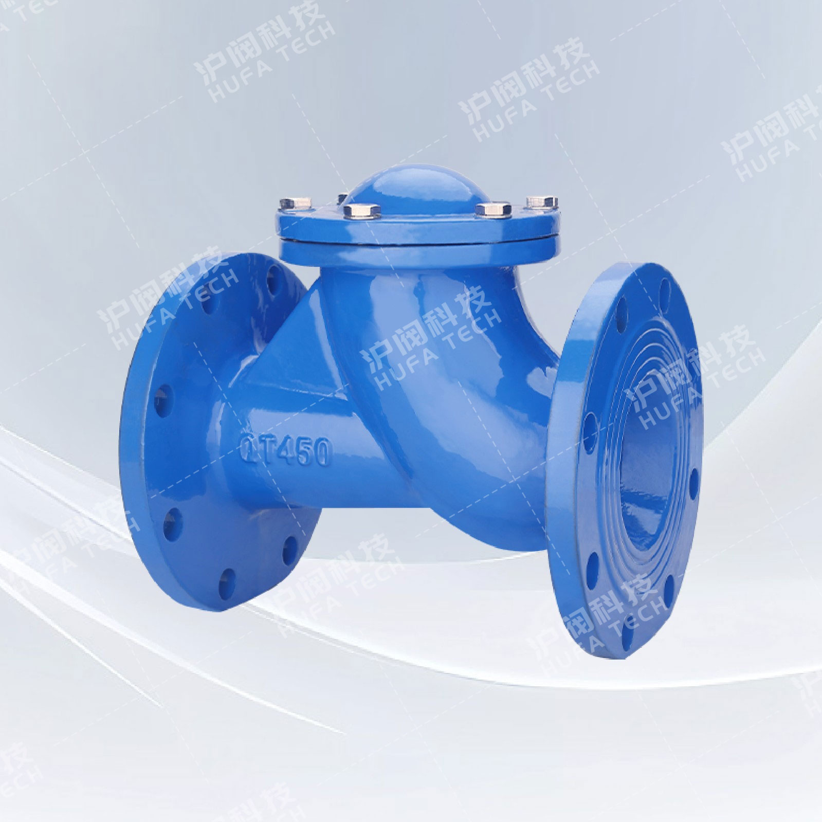
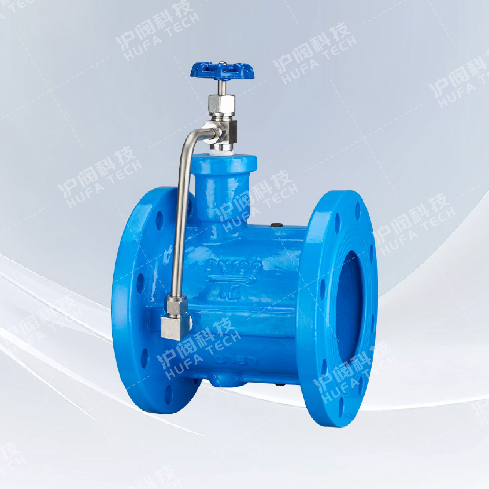
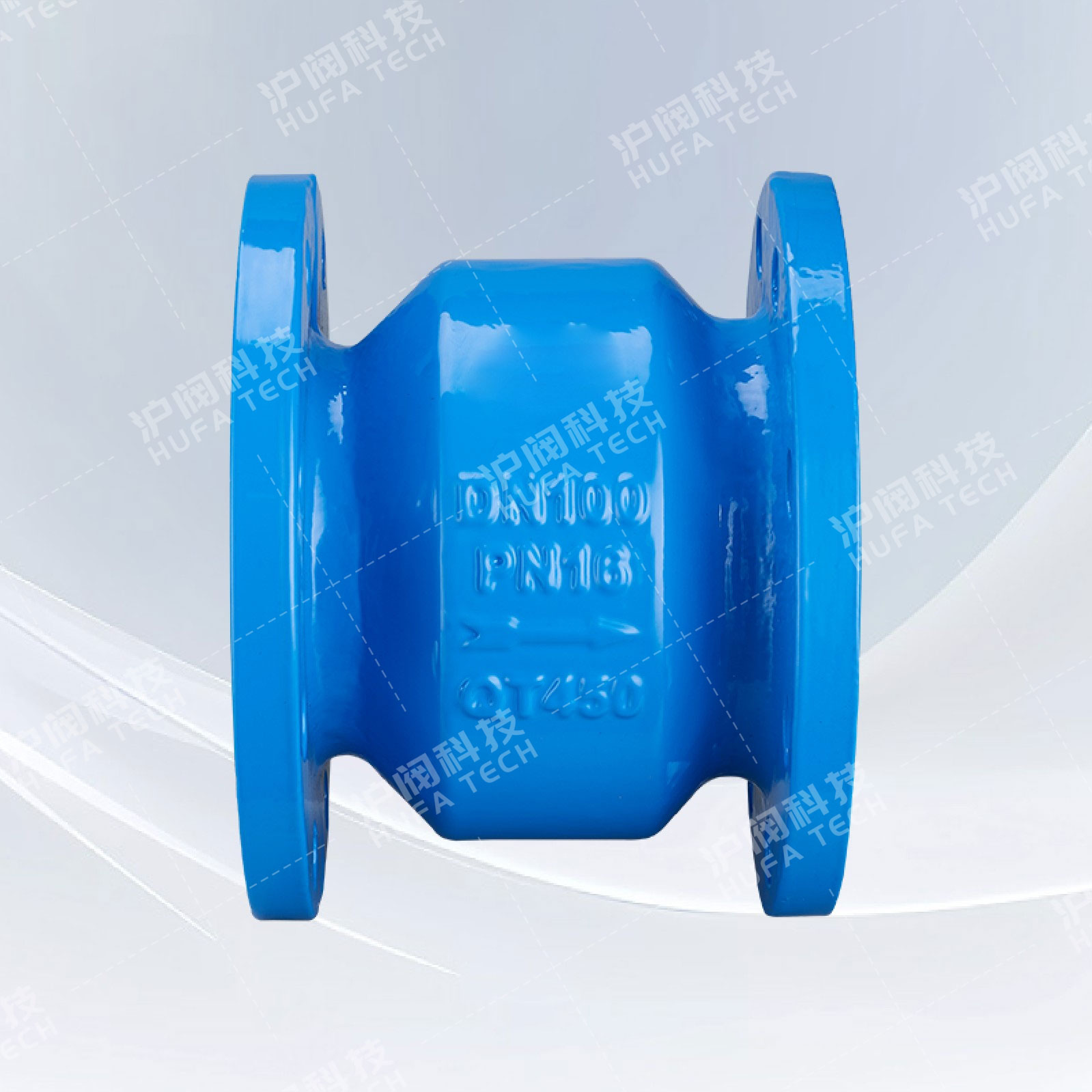
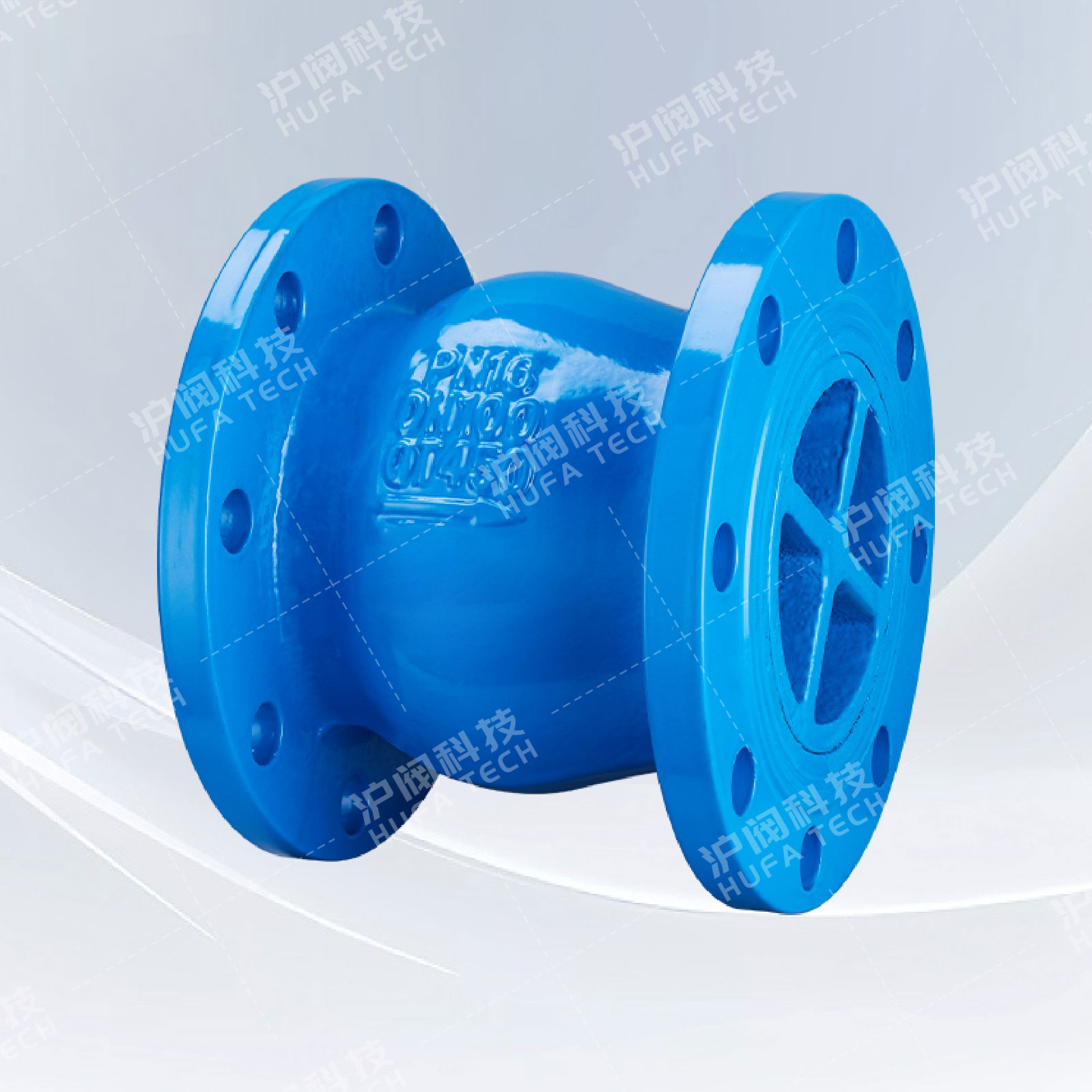
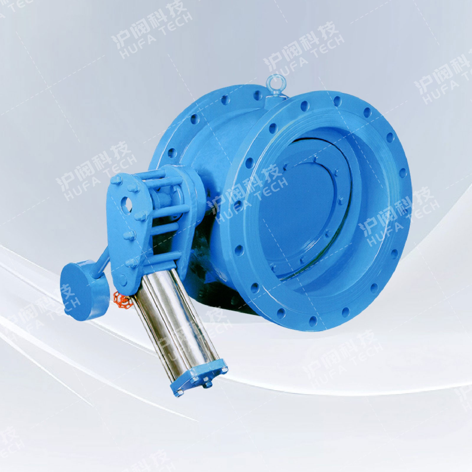
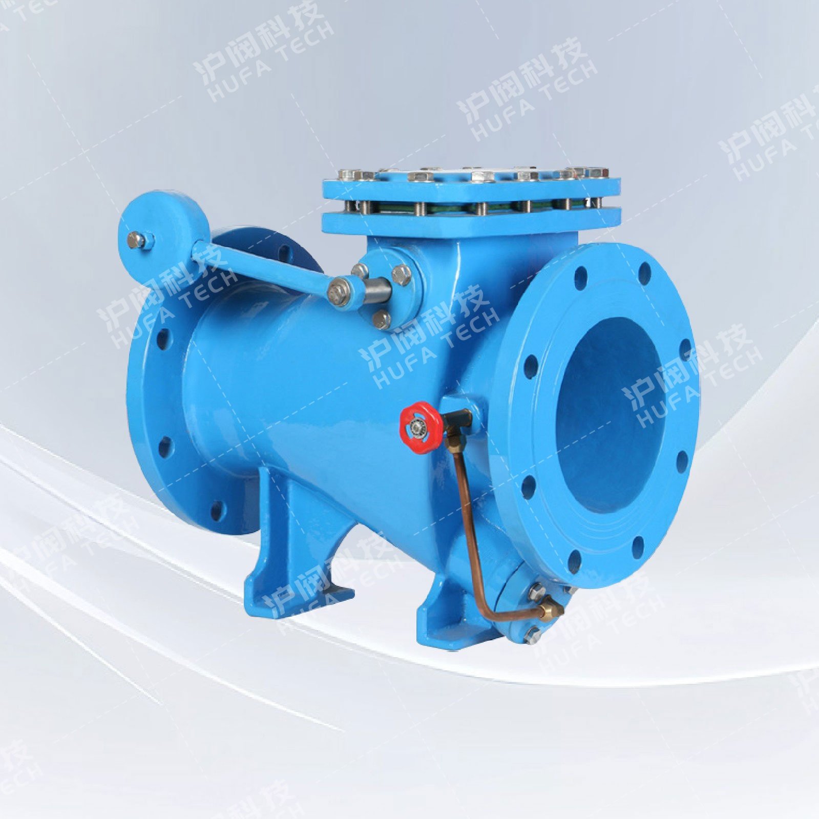
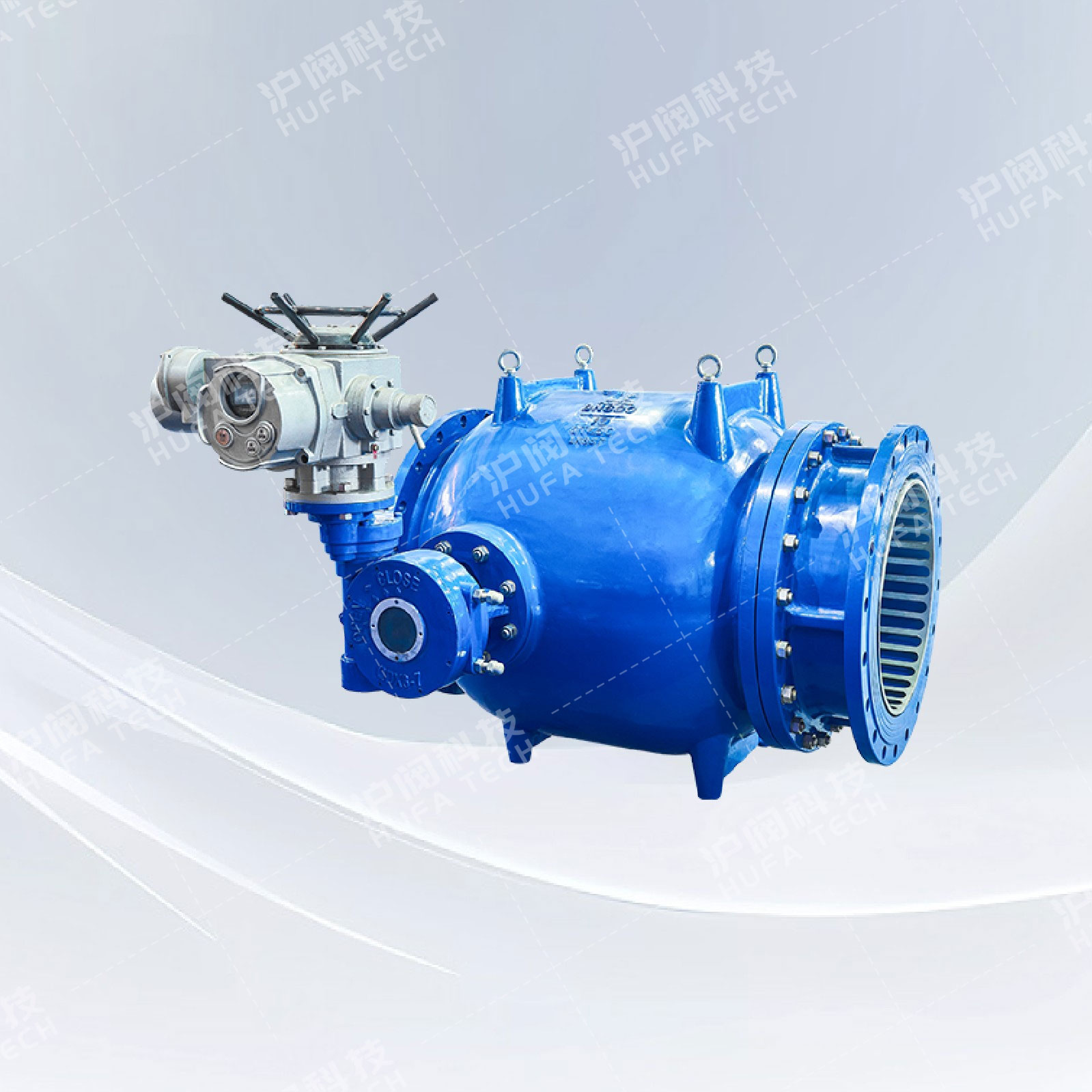
Diaphragm type inclined-seated multi-functional liquid control check valve
Technical Specifications
Product model: BFDZ701HR
Fluid medium: Water, liquid
Applicable temperature range: -10℃ to 120℃
Applicable pressure: PN0.6 to 1.6 MPa
Connection standards: GB·ANSI·DIN·API·ISO·BS
Valve body material: Spheroidal graphite cast iron; Carbon steel; Stainless steel; Corrosion-resistant valve body components, blue epoxy resin coating
Valve seat material: Stainless steel; Rubber
Valve plate material: Carbon steel; Stainless steel; Ductile iron
Note: All components can be selected with different materials according to actual working conditions.
Sales Hotline:
Product Details
Technical standards
The test complies with the standard GB/T13927-2008 "Pressure Test for Industrial Valves".
The side flange connection complies with the GB/T17241.6-2008 "Integral Cast Iron Flange" standard. It also meets the PN1.0MPa and PN1.6MPa flange connection standards specified in BS4504, ISO7005, and DIN2501.
The 13 series complies with the dimensions specified in GB/T12221-2005 "Structural Dimensions of Metal Valves" for flanged connection butterfly valves of the 13 series.
The 14 series complies with the dimensions specified in GB/T12221-2005 "Structural Dimensions of Metal Valves" for flanged connection butterfly valves of the 14 series.
Features and advantages
The valve plate adopts a large inclination design, with the valve seat placed at an angle. This effectively improves the response speed of the valve to the direction of the medium flow, and better utilizes the flow force and gravity of the medium. At the same time, the truss-shaped streamlined design of the valve plate can increase the flow area, reduce the flow resistance coefficient, and lower the operating cost.
Adopting an eccentric pendulum structure and an external buffering mechanism;
The valve plate adopts a double eccentric swing structure, which is beneficial for reducing flow resistance and vibration.
The buffer damping cylinder effectively controls the closing speed of the valve, reduces and eliminates water hammer. When in use, it has no vibration, no noise and operates smoothly.
Fully self-adaptive flow switch, without external operating system, low carbon and environmentally friendly.
No matter where the piston is located, the contraction flow section remains circular, thus ensuring perfect linear adjustment characteristics.
|
PN |
DN |
L |
D |
K |
N-Φ |
E |
F |
J |
M |
G |
H |
L1 |
L2 |
N-Φ |
|
PN6 |
1200 |
630 |
1405 |
1340 |
32-Φ34 |
880 |
1230 |
1040 |
941 |
1180 |
920 |
287 |
570 |
4-Φ26 |
|
1400 |
710 |
1630 |
1560 |
36-Φ37 |
995 |
1380 |
1500 |
1009 |
1180 |
870 |
287 |
665 |
4-Φ33 |
|
|
1600 |
790 |
1830 |
1760 |
40-Φ37 |
1078 |
1525 |
1600 |
1225 |
1420 |
1060 |
344 |
775 |
4-Φ33 |
|
|
1800 |
870 |
2045 |
1970 |
44-Φ40 |
1125 |
1575 |
1900 |
1290 |
1420 |
1010 |
344 |
885 |
4-Φ33 |
|
|
PN10 |
300 |
270 |
445 |
400 |
12-Φ23 |
300 |
485 |
380 |
605 |
500 |
490 |
116 |
75 |
4-Φ20 |
|
350 |
290 |
505 |
460 |
16-Φ23 |
320 |
510 |
400 |
634 |
500 |
470 |
116 |
103 |
4-Φ20 |
|
|
400 |
310 |
565 |
515 |
16-Φ28 |
330 |
540 |
442 |
693 |
500 |
470 |
116 |
130 |
4-Φ20 |
|
|
450 |
330 |
615 |
565 |
20-Φ28 |
355 |
585 |
450 |
753 |
590 |
510 |
170 |
157 |
4-Φ20 |
|
|
500 |
350 |
670 |
620 |
20-Φ28 |
380 |
645 |
490 |
832 |
590 |
495 |
170 |
185 |
4-φ20 |
|
|
600 |
390 |
780 |
725 |
20-Φ31 |
440 |
725 |
672 |
941 |
590 |
490 |
170 |
240 |
4-φ20 |
|
|
700 |
430 |
895 |
840 |
24-Φ31 |
498 |
808 |
700 |
1009 |
770 |
560 |
211 |
295 |
4-Φ20 |
|
|
800 |
470 |
1015 |
950 |
24-Φ34 |
570 |
850 |
790 |
1225 |
770 |
540 |
211 |
350 |
4-Φ26 |
|
|
900 |
510 |
1115 |
1050 |
28-Φ34 |
638 |
935 |
870 |
1290 |
920 |
785 |
236 |
405 |
4-Φ26 |
|
|
1000 |
550 |
1230 |
1160 |
28-Φ37 |
695 |
1050 |
950 |
|
920 |
765 |
236 |
460 |
4-Φ26 |
|
|
1200 |
630 |
1455 |
1380 |
32-Φ40 |
880 |
1230 |
1040 |
|
1180 |
920 |
287 |
570 |
4-Φ26 |
|
|
1400 |
710 |
1675 |
1590 |
36-Φ43 |
995 |
1380 |
1500 |
|
1180 |
870 |
287 |
665 |
4-Φ33 |
|
|
1600 |
790 |
1915 |
1820 |
40-Φ49 |
1078 |
1525 |
1600 |
|
1420 |
1060 |
344 |
775 |
4-Φ33 |
|
|
1800 |
870 |
2115 |
2020 |
44-Φ49 |
1125 |
1575 |
1900 |
|
1420 |
1010 |
344 |
885 |
4-Φ33 |
|
|
PN16 |
300 |
270 |
460 |
410 |
12-Φ28 |
300 |
485 |
380 |
605 |
500 |
490 |
116 |
75 |
4-Φ20 |
|
350 |
290 |
520 |
470 |
16-Φ28 |
320 |
510 |
400 |
634 |
500 |
470 |
116 |
103 |
4-Φ20 |
|
|
400 |
310 |
580 |
525 |
16-Φ31 |
330 |
540 |
442 |
693 |
500 |
470 |
116 |
130 |
4-Φ20 |
|
|
450 |
330 |
640 |
585 |
20-Φ31 |
355 |
585 |
450 |
753 |
590 |
510 |
170 |
157 |
4-Φ20 |
|
|
500 |
350 |
715 |
650 |
20-Φ34 |
380 |
645 |
490 |
832 |
590 |
495 |
170 |
185 |
4-Φ20 |
|
|
600 |
390 |
840 |
770 |
20-Φ37 |
440 |
725 |
672 ; |
941 |
590 |
490 |
170 |
240 |
4-φ20 |
|
|
700 |
430 |
910 |
840 |
24-Φ37 |
498 |
808 |
700 |
1009 |
770 |
560 |
211 |
295 |
4-Φ20 |
|
|
800 |
470 |
1025 |
950 |
24-Φ40 |
570 |
850 |
790 |
1225 |
770 |
540 |
211 |
350 |
4-Φ26 |
|
|
900 |
510 |
1125 |
1050 |
28-Φ40 |
638 |
935 |
870 |
1290 |
920 |
785 |
236 |
405 |
4-Φ26 |
|
|
1000 |
550 |
1255 |
1170 |
28-Φ43 |
695 |
1050 |
950 |
|
920 |
765 |
236 |
460 |
4-Φ26 |
 Check the mobile website