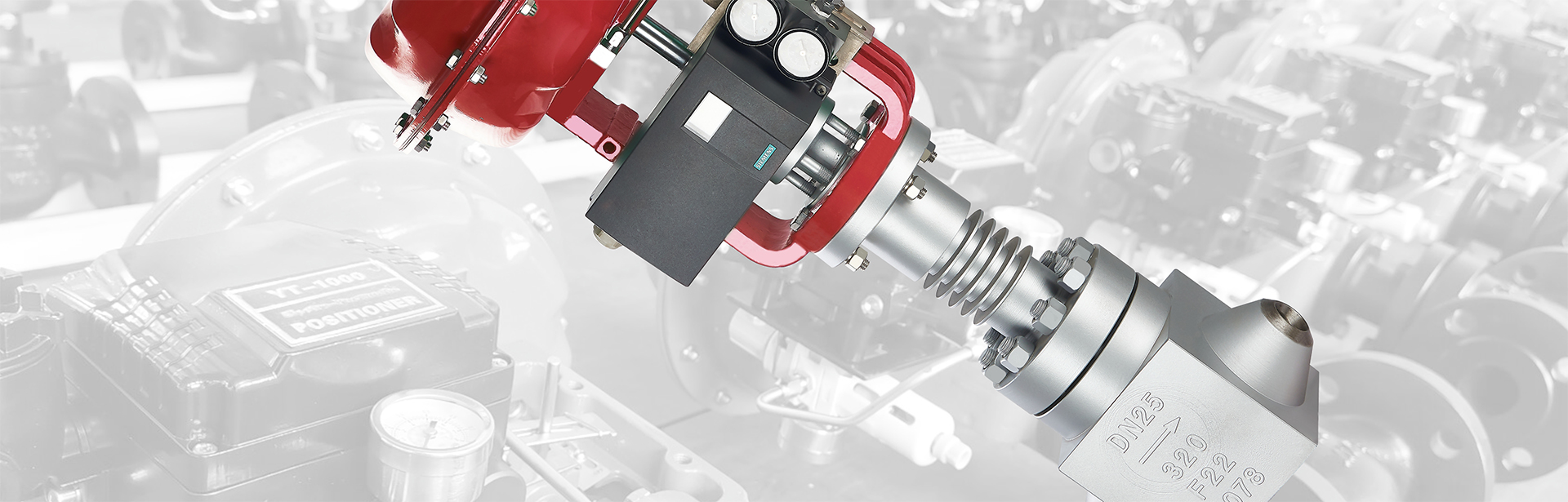
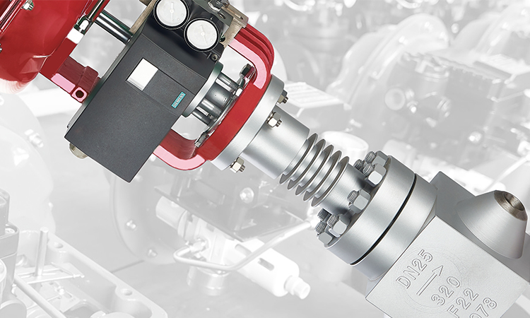

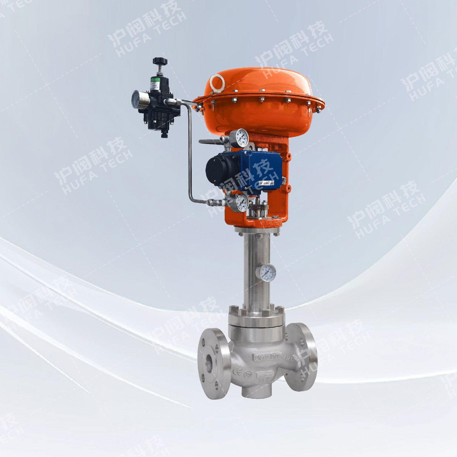
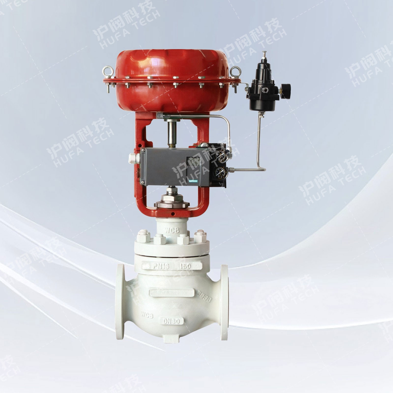
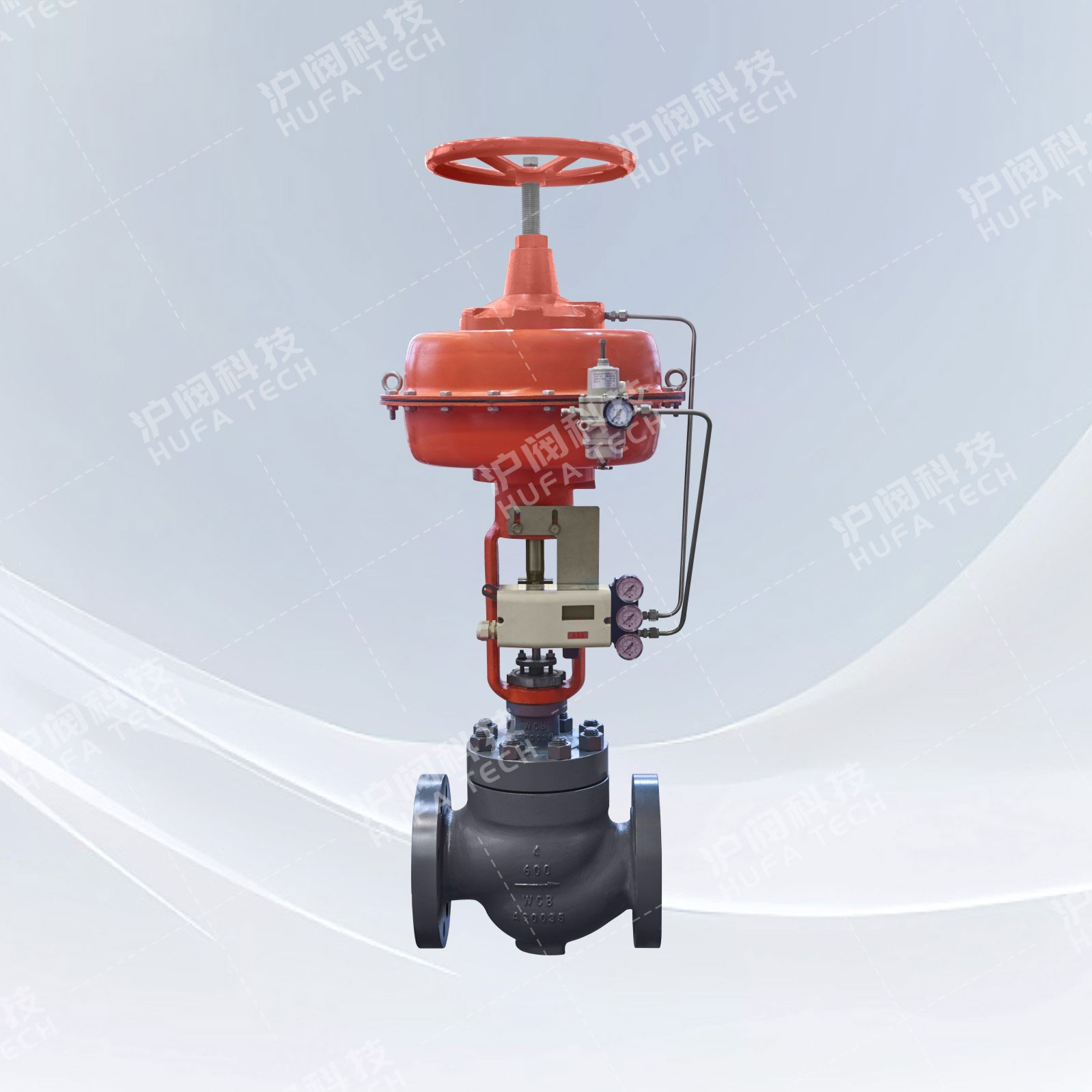
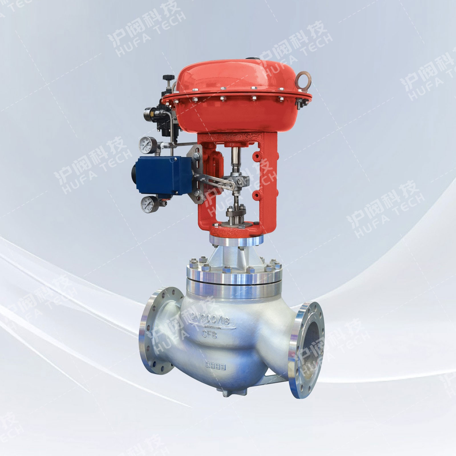
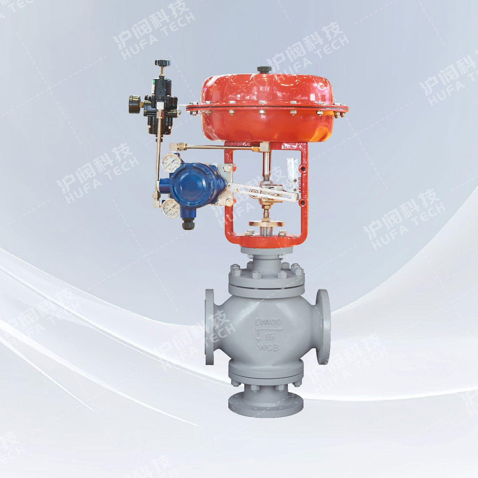
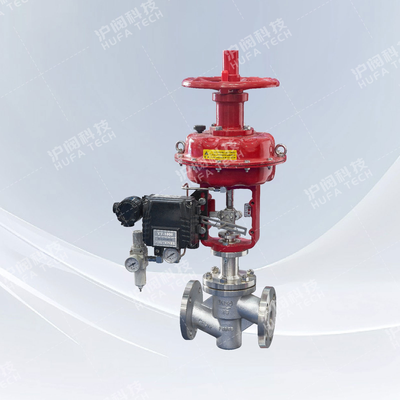
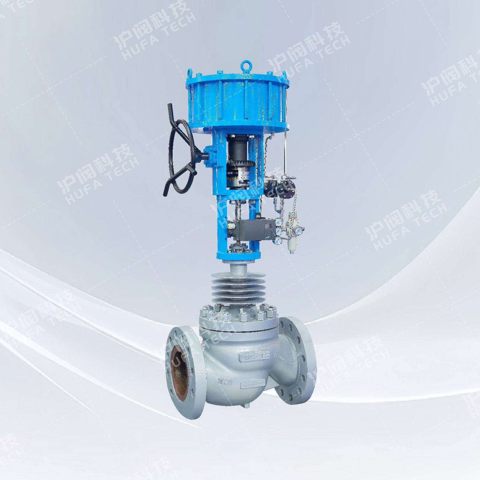
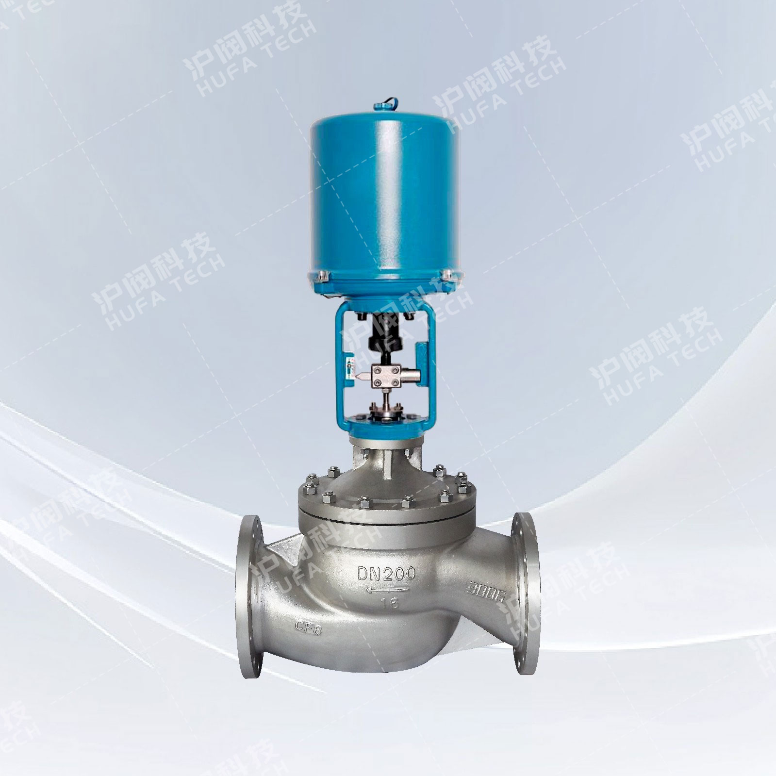
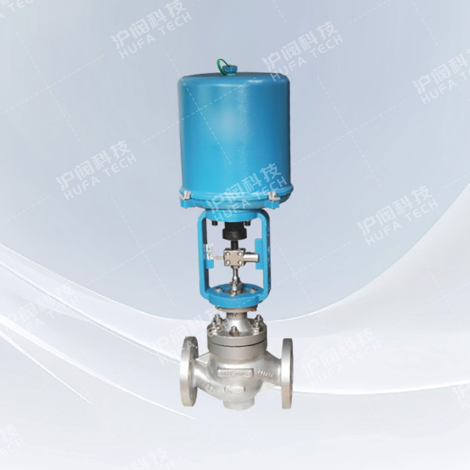
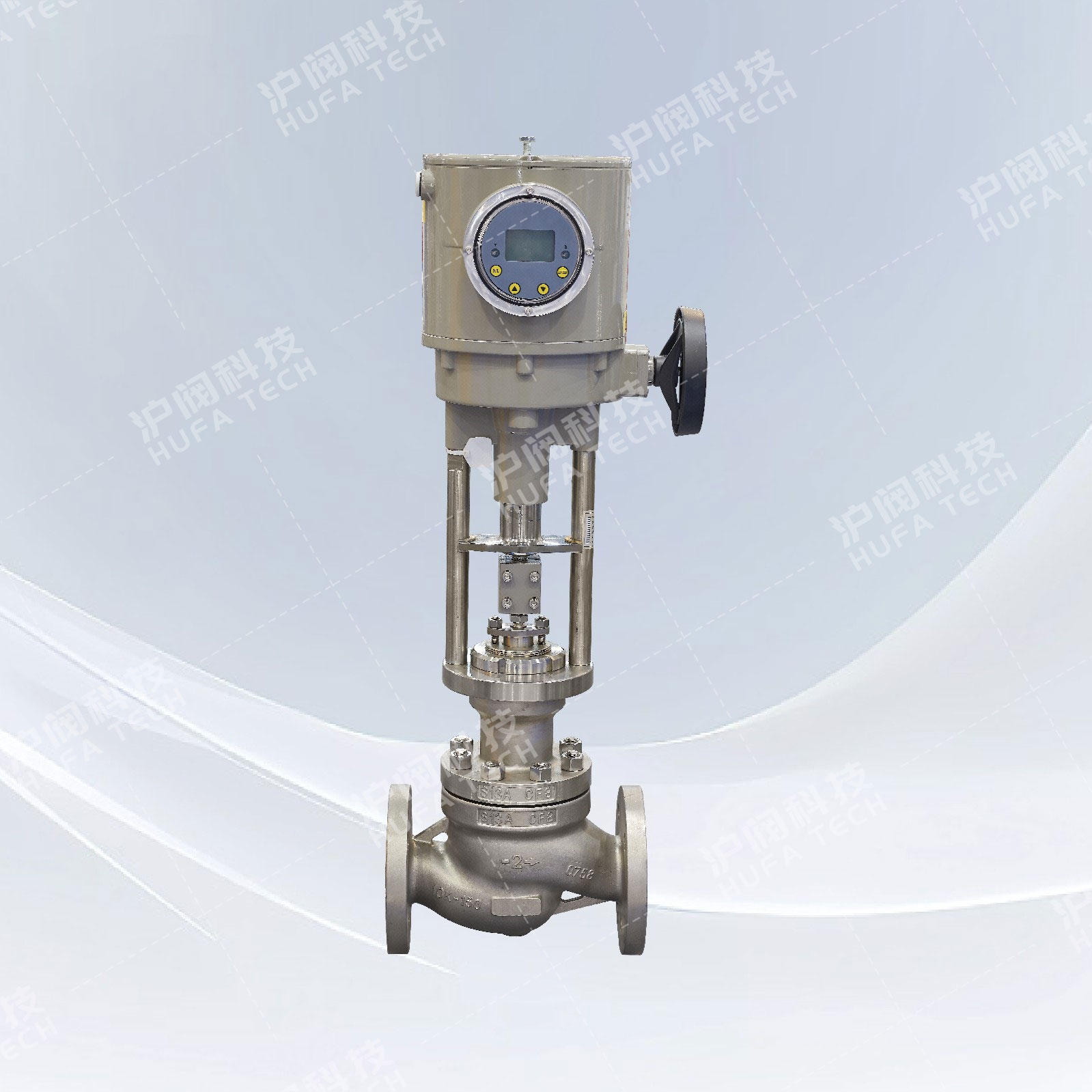
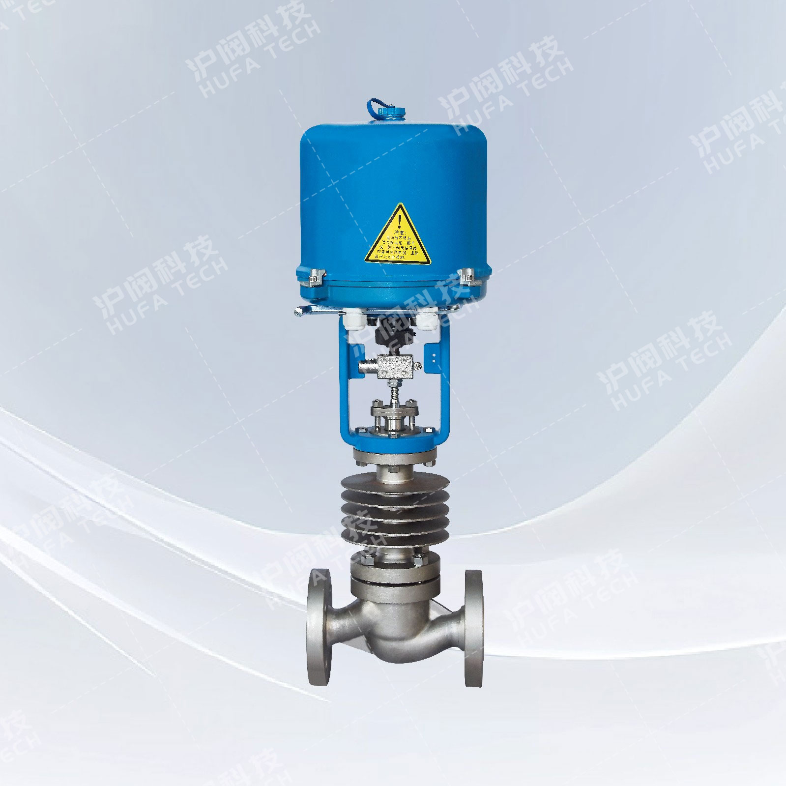
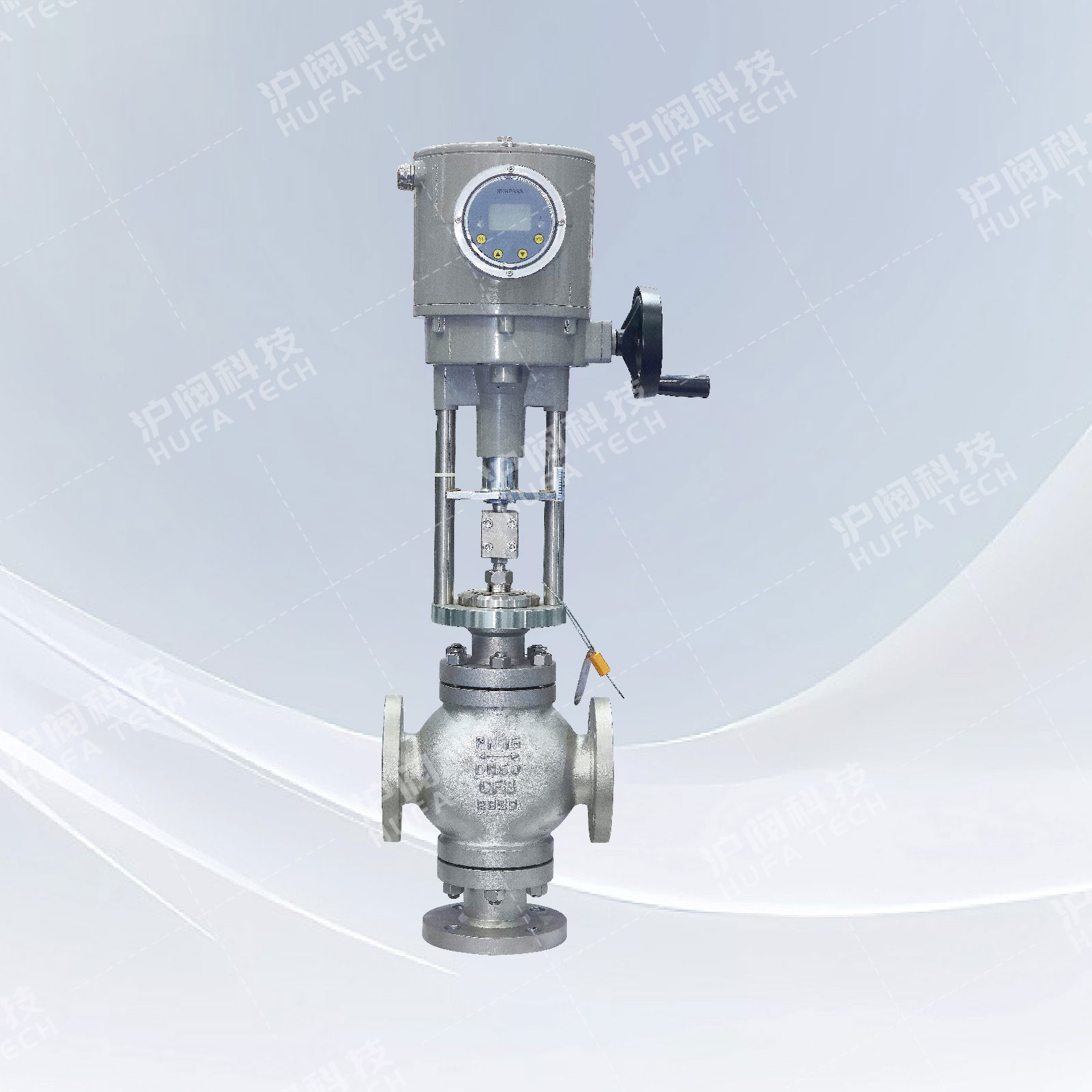
Pneumatic Bellows Control Valve
Technical Specifications
Product model: ZJHB (P/M)
Nominal diameter: DN25~300mm
Pressure range: PN1.6~6.4MPa
Operating temperature: -40℃~+350℃
Technical standard: IEC534-1-1976
Flange standard: JB/T79-2015
Valve form: straight-through cast ball valve
Body Material: Cast Steel (WCB) Stainless Steel (CF8)
Sealing packing: bellows seal, V-type PTFE
Sales Hotline:
Product Details
Product Description
Pneumatic bellows regulating valve is composed of multi-spring pneumatic membrane actuator and bellows sealing regulating valve body. The spool of the bellows control valve adopts an upper guide structure, which is compact in structure and has an S-streamline flow channel, which makes the pressure drop loss small, the flow rate is large, the adjustable range is wide, and the flow characteristic accuracy is high. The upper bonnet adopts a bellows sealing structure. , to ensure the sealing performance. It is suitable for the regulation of flammable, explosive, volatile, highly permeable and rare precious metal media. In addition, the pneumatic bellows regulating valve can also be used in vacuum applications.
Product Features
1. The double sealing structure of bellows packing is adopted to achieve better safety and reliability without leakage; more reasonable material matching can be selected according to the temperature or pressure of on-site use.
2. It is suitable for the regulation of flammable, explosive, volatile, highly permeable and rare precious metal media. The bellows packing double seal can also be used for regulation on vacuum piping.
The main technical parameters
| DN | 20 | 25 | 32 | 40 | 50 | 65 | 80 | 100 | 125 | 150 | 200 | 250 | 300 | |
| Seat Diameter(dn) | 20 | 25 | 32 | 40 | 50 | 65 | 80 | 100 | 125 | 150 | 200 | 250 | 300 | |
| KV | Single seat | 6.9 | 11 | 17.6 | 27.5 | 44 | 69 | 110 | 176 | 275 | 440 | 630 | 875 | 1250 |
| Sleeve | 6.3 | 10 | 16 | 25 | 40 | 63 | 100 | 155 | 250 | 370 | 580 | 900 | 1300 | |
| Allowable differential pressure(MPa) | Single seat | 3.8 | 3.2 | 3.0 | 2.0 | 1.8 | 1.5 | 1.4 | 1.0 | 0,7 | 0.6 | 0.5 | 0.3 | 0.1 |
| Sleeve | 6.4 | 6.4 | 5.2 | 5.2 | 4.6 | 4.6 | 3.7 | 3.7 | 3.5 | 3.1 | 3.1 | 2.6 | 2.2 | |
| PN(MPa) | 1.6、2.5、4.0、6.4 | |||||||||||||
| L(mm) | 16 | 25 | 40 | 60 | 100 | |||||||||
| Actuator model | ZHA/B-22 | ZHA/B-23 | ZHA/B-34 | ZHA/B-45 | ZHA/B-56 | |||||||||
| Bonnet form | Bellows seal type -40~+350℃ | |||||||||||||
| Gland form | Bolt compression | |||||||||||||
| seal packing | V-type PTFE packing, V-type flexible graphite packing | |||||||||||||
| Spool form | Single seat type, sleeve type | |||||||||||||
| Flow characteristics | Equal percentage, straight | |||||||||||||
Actuator technical parameters
| Configure Actuator Class | ZHA/B multi-spring diaphragm actuator | ||||
| Actuator model | ZHA/B-22 | ZHA/B-23 | ZHA/B-34 | ZHA/B-45 | ZHA/B-56 |
| Effective area(cm2) | 350 | 350 | 560 | 900 | 1400 |
| L(mm) | 10、16 | 24 | 40 | 40、60 | 100 |
| Spring range(KPa) | 20~100(standard)、20-60、60-100、40-200、80-240 | ||||
| Diaphragm material | Nitrile rubber with nylon cloth, ethylene propylene rubber with nylon cloth | ||||
| Air supply pressure | 140~400KPa | ||||
| Air supply interface | RC1/4" | ||||
| ambient temperature | -30~+70℃ | ||||
| Accessories available | Positioner, air filter pressure reducer, position retaining valve, travel switch, valve position transmitter, hand wheel mechanism, etc. | ||||
| Form of action | Air-to-close (B)—valve open (FO) when gas is lost; air-to-open (K)—valve to be closed when gas is lost (FC) | ||||
Main performance indicators
| Project | Without locator | With locator | ||
| Basic error% | ±5.0 | ±1.0 | ||
| Return difference% | 3.0 | 1.0 | ||
| Dead zone% | 3.0 | 0.4 | ||
| Always point deviation% | Electric switch | Start point | ±2.5 | ±1.0 |
| Start point | ±5.0 | ±1.0 | ||
| Air to close | Start point | ±5.0 | ±1.0 | |
| Snd | ±2.5 | ±1.0 | ||
| Rated stroke deviation % | ≤2.5 | |||
| Leakage L/h | 0.01%×valve rated capacity | |||
| Adjustable range R | 30:1 | |||
Material of main parts
| 1 | Body | WCB | 304 | 316 | 316L |
| 2 | Gasket | PTFE\Graphite Gasket | PTFE\Graphite Gasket | PTFE\Graphite Gasket | PTFE\Graphite Gasket |
| 3 |
Seat / Sleeve |
304 | 304 | 316 | 316L |
| 4 | Spool | 304 | 304 | 316 | 316L |
| 5 | Guide sleeve / cap | 304 | 304 | 316 | 316L |
| 6 | Middle pad | PTFE\Graphite Gasket | PTFE\Graphite Gasket | PTFE\Graphite Gasket | PTFE\Graphite Gasket |
| 7 | Cap | WCB | 304 | 316 | 316L |
| 8 | Stem | 304 | 304 | 316 | 316L |
| 9 | Bellows | 304 | 304 | 316 | 316L |
| 10 | Filler | PTFE/Graphite | PTFE/Graphite | PTFE/Graphite | PTFE/Graphite |
| 11 | Packing gland | WCB | 304 | 316 | 316L |
Main external connection dimensions
| DN(mm) | 20 | 25 | 32 | 40 | 50 | 65 | 80 | 100 | 125 | 150 | 200 | |
| L | PN16/25 | 181 | 184 | 200 | 222 | 254 | 276 | 298 | 352 | 410 | 451 | 600 |
| PN40 | 194 | 197 | 200 | 235 | 267 | 292 | 317 | 368 | 425 | 473 | 610 | |
| PN64 | 206 | 200 | 210 | 251 | 286 | 311 | 337 | 394 | 440 | 508 | 650 | |
| H | PN16/25 | 52.5 | 57.5 | 75 | 75 | 85.5 | 92.5 | 100 | 110 | 142.5 | 158 | 170 |
| PN40 | 52.5 | 57.5 | 75 | 75 | 82.5 | 92.5 | 100 | 117.5 | 150 | 167.5 | 187.5 | |
| PN64 | 65 | 40 | 85 | 85 | 90 | 102.5 | 107.5 | 125 | 172.5 | 195 | 207.5 | |
| H1 | 365 | 365 | 425 | 430 | 445 | 660 | 680 | 690 | 748 | 740 | 780 | |
| H2 | 298 | 298 | 298 | 298 | 298 | 380 | 380 | 380 | 510 | 510 | 510 | |
| H3 | 180 | 180 | 180 | 180 | 180 | 236 | 236 | 236 | 310 | 310 | 310 | |
| L1 | 289 | 289 | 289 | 289 | 289 | 347 | 347 | 347 | 476 | 476 | 476 | |
| A | 282 | 282 | 282 | 282 | 282 | 360 | 360 | 360 | 470 | 470 | 470 | |
| D | 220 | 220 | 220 | 220 | 220 | 270 | 270 | 270 | 320 | 320 | 320 | |
 Check the mobile website